Quantcast
Channel: EEP – Electrical Engineering Portal
Viewing all 1385 articles
Browse latest View live

Switching Impulse Test of the Transformer

$
0
0


Switching Impulse Test of the Transformer

Switching Impulse Test of the Transformer (on photo Mississippi State University High Voltage Laboratory as University Research Center)
Purpose of the Test

The switching impulse test is applied to confirm the withstand of the transformer’s insulation against excessive voltages occuring during switching. During switching impulse voltage test, the insulation between windings and between winding and earth and withstand between different terminals is checked.

The purpose of the switching impulse test as special test is to secure that the insulations between windings, between windings and earth, between line terminals and earth and between different terminals withstand the switching overvoltages, which may occur in service.

The switching impulse voltage is generated in conventional impulse voltage generators at the laboratories.

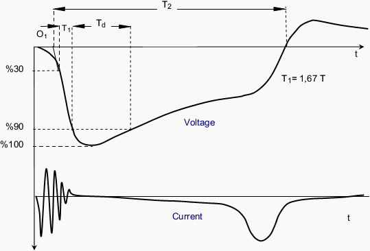
The polarity of the voltage is negative and the voltage waveform should normally be T1/ Td/ T2 20/200/500 μS (fiigure 2) according to IEC 60076-3.

Due to over-saturation of the core during switching impulse test, a few low amplitude, reverse polarity (e.g. positive) impulses are applied after each test impulse in order to reset the transformer core to it’s starting condition (demagnetised). By this way,the next impulse voltage waveform is applied. The tap position of the transformer during test is determined according to test conditions.

The on-off impulse voltages are applied to each high voltage terminal sequentially.

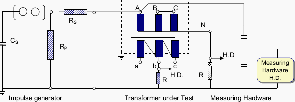
Switching on-off impulse test connection diagram

Figure 1 - Switching on-off impulse test connection diagram


Meanwhile, the neutral terminal is earthed. The windings which are not under test are left open (earthed at one point). This connection is similar to the induced voltage test connection. The voltage distribution on the winding is linear like the induced voltage test and the voltage amplitudes at the un-impulsed windings are induced according to the turn ratio.

Meanwhile, necessary arrangements should be made since the voltage between phases will be 1,5 times the phase-neutral voltage.

The test circuit connections of three phase transformers depend on; structure of the core (three or five legged), the voltage level between phases and the open or closed state of the delta winding (if any). At first, a voltage with 50 % decresed value is used at the tests,then impulse voltages at full values and at numbers given in standards are used. The peak value of the voltage is measured.

The change of the voltage waveform and winding current are measured with a special measuring instrument and recorded. The negativities in the transformer during the test are determined by comptring the voltage and current oscillograms.

Switching impulse voltage waveform

Figure 2 - Switching impulse voltage waveform


The sudden collapses of the voltage (surges) and abnormal sounds show deformation of the insulation in the transfomer. The deformation of the voltage waveform and increase in noise due to magnetic saturation of the core should not be considered as fault.

The test voltage values, impulse shapes, and number of impulses at different voltage levels must be stated in the report.

Switching Impulse Voltage Waveform :

Front : T1 ≥100 µS = 1,67 T
90% value : Td ≥ 200 µS
Time for cutting the axis : T2 ≥ 500 µS

Resource: Transformer tests – BALIKESİR ELEKTROMEKANİK SANAYİTESİSLERİA.Ş.


NEC Requirements for Emergency Systems

$
0
0


NEC Requirements for Emergency Systems

NEC Requirements for Emergency Systems (on photo Automatic Transfer Switch for Emergency Systems 240V 150A 3p)

Introduction

Emergency systems are generally installed in buildings that are or can be occupied by 1000 or more persons or are more than 75 ft high.

These are buildings where artificial illumination is required for safe exiting and for panic control. Examples are hotels, theaters, airports, railroad stations, sports arenas, department stores, and hospitals.

Emergency systems are designed to power exit lighting, fire detection and alarm systems, elevators, fire pumps, and public safety communications systems. They might also power ventilation systems considered essential to preserving health and life, or industrial processes where power interruption would result in hazards to life or injury.

NEC 2012, Article 700, “Emergency Systems,” covers electrical safety in the installation, operation, and maintenance of emergency systems. These consist of “circuits and equipment intended to supply, distribute, and control electricity for illumination, power or both, to vital facilities when the normal electrical supply or system is interrupted”.

These are “systems legally required and classed as emergency by municipal, state, federal, or others codes, or by any governmental agency having jurisdiction”.

These systems are intended to automatically supply illumination, power, or both to designated areas and equipment in the event of failure of the normal supply or in the event of accident to elements of a system intended to supply, distribute, and control power and illumination essential to human life.”

The general subjects covered in Article 700 include:

  • Tests and maintenance of approved emergency system equipment
  • Capacity and rating of emergency system equipment
  • Power transfer equipment, including automatic transfer switches
  • Signals and signs for emergency systems

The circuit wiring provisions of Article 700 include:

  • Identification of boxes, enclosures, transfer switches, generators, etc.
  • Wiring independence and exceptions
  • Fire protection for high-occupancy and high-rise buildings

The section on sources of power gives the response-time requirements for the restoration of emergency lighting, emergency power, or both as “not to exceed 10 seconds” for the specific classes of buildings stated previously.

In selecting the emergency source of power, consideration must be given to the occupancy and type of service rendered in those buildings.

The occupancy classes are given as (1) assembly, (2) educational, (3) residential, (4) detention and correctional, (5) business, and (6) mercantile.

Article 700 requires that power sources be installed in rooms protected by approved automatic fire suppression systems (sprinklers, CO2systems, etc.) or in spaces with a 1-hr burn rating. (Fire can surround or be adjacent to the room for at least 1 hr before its fire-resistant integrity is lost and its contents begin to ignite spontaneously.)

The four emergency power systems approved by Article 700 are:

  • Storage batteries (rechargeable)
  • Generator sets
  • Uninterruptible power supplies (UPS)
  • Separate services (alternate outside utility or inside generation) in accordance with NEC Article 230

The section on emergency system circuits for lighting and power covers:

  • Approved loads on emergency branch circuits
  • Emergency illumination
  • Circuits for emergency lighting
  • Circuits for emergency power

The section on emergency control lighting circuits covers:

  • Switch requirements
  • Switch location
  • Exterior lights

The section on overcurrent protection covers accessibility of branch-circuit overcurrent devices (fuses and circuit breakers) and ground-fault protection of equipment.

Resource: National Electrical Code Handbook; Handbook of Electrical Design – Neil Sclater (buy this book at Amazon)

Difference Between Diffuse and Directed Light

$
0
0


Difference Between Diffuse and Directed Light

Difference Between Diffuse and Directed Light (on photo Light Building 2012 Frankfurt LIQUID_LIGHT by Hopf & Wortmann)

Introduction

Having dealt with light quantity, conside-ration must be given to the quality of light, the difference between diffuse light and directed light being one of the most important aspects. We are familiar with these different forms of light through our everyday experience with daylight – direct sunlight when the sky is clear and diffuse light when the sky is overcast.

Characteristic qualities are the uniform, almost shadowless light we experience under an overcast sky, in contrast to the dramatic interplay of light and shade in bright sunlight.

Diffuse light is produced by extensive areas that emit light. These may be extensive, flat surfaces, such as the sky in the day-time, or, in the field of artificial lighting, luminous ceilings. In interior spaces diffuse light can also be reflected from illuminated ceilings and walls.

This produces very uniform, softlighting, which illuminates the entire space and makes objects visible, but produces reduced shadows or reflections.

Directed light is emitted from point light sources. In the case of daylight this is the sun,in artificial lighting compact light sources. The essential properties of directed light are the production of shadows on objects and structured surfaces, and reflections on specular objects. These effects are particularly noticeable when the general lighting consists of only a small portion of diffuse light.

Daylight used for lighting

Daylight used for lighting (photo by BNIM Architects)

Daylight, for example, has a more or less fixed ratio of sunlight to sky light (directed light to diffuse light) of 5:1 to 10:1. In interior spaces, on the other hand, we can determine the ratio of directed and diffuse light we require or prefer.

The portion of diffuse light decreases when ceiling and walls receive too little light, or when the light falling on a surface is absorbed to a large extent by the low reflectance of the environment.

This can be exploited for dramatic effects through accent lighting. This technique is often applied for the presentation of objects, but is only used in architectural lighting when the concept intends to create a dramatic spatial effect.

Directed light not only produces shadows and reflections; it opens up new horizons for the lighting designer because of the choice of beam angles and aiming directions that he has at his disposal.

Where as the light emitted by diffuse or exposed light sources always has an effect on the entire space, in the case of tightly controlled light, the effect of the light relates directly to the position of the luminaire.

Here lies one of the most progressive aspects of lighting technology. Whereas in the era of the candle and the oil lamp the light was bound to the immediate vicinity of the luminaire, it is now possible to use light in other parts of the space at any distance from where the light source is located.

It is possible to use lighting effects at specific illuminance levels on exactly defined areas from practically any location within a space.

This means that a space can be purposefully lit and the lighting modulated. The relative local illuminance level can be adjusted to suit the significance of a particular part of a space and the perceptual information it contains.

Modelling

Another basic feature of the world around us, and one that we take absolutely for granted, is its three-dimensional quality.

One essential objective regarding visual perception must therefore be to provide information about this aspect of our environment. Three-dimensionality comprises a number of individual areas, from the extension of the space around us to the location and orientation of objects within the space, down to their spatial form and surface structure.

Perception of the three-dimensional character of our environment involves processes that relate to our physiology and perceptual psychology. The shaping of our environment through light and shade is of prime importance for our perception of spatial forms and surface structures.

Modelling is primarily effected using directed light.

This has been referred to, but the significance for human perception must be analysed.

If we view a sphere under completely diffuse light we cannot perceive its spatial form. It appears to be no more than a circular area. Only when directed light falls on the sphere – i.e. when shadows are created, can we recognise its spatial quality.

The same applies to the way we perceive surface structures. These are difficult to recognise under diffuse light. The texture of a surface only stands out when light is directed onto the surface at an angle and produces shadows.

Only through directed light are we able to gain information about the three-dimensional character of objects. Just as it is impossible for us to retrieve this information when there is no directed light at all, too much shaping can conceal information. This happens when intensely directed light casts such stark shadows that parts of an object are concealed by the darkness.

Perception of three-dimensional forms and surface structures under different lighting conditions

Perception of three-dimensional forms and surface structures under different lighting conditions. Directed light produces pronounced shadows and strong shaping effects. Forms and surface structures are accentuated, while details can be concealed by the shadows.

Lighting that consists of both diffuse and directed lighting

Lighting that consists of both diffuse and directed lighting produces soft shadows. Forms and surface structures can be recognised clearly. There are no disturbing shadows.

Diffuse lighting produces negligible shadowing

Diffuse lighting produces negligible shadowing. Shapes and surface structures are poorly recognisable.


The task of lighting design is therefore to create a suitable ratio of diffuse light to directed light to meet the requirements of each individual situation. Specific visual tasks, where the spatial quality or the surface structure is of prime importance, require lighting that emphasises shapes and forms. Only in situations where spatial quality and surface structure are of no importance, or if they are disturbing factors, can completely diffuse lighting be used.

As a rule suitable proportions of diffuse light and directed light are required.

Well balanced portions provide good overall visibility of the environment and simultaneously allow spatial appreciation and vivid perception of the objects.

In some standards for workplace lighting there is a criterion for the modelling effect of a lighting installation. It is referred to as the modelling factor, which is defined as the ratio of cylindrical illuminance to horizontal illuminance. When planning the application of directed and diffuse light it is advisable to rely on our fundamental experience of daylight with regard to the direction and colour of the light.

Direct sunlight either comes from above or from the side, but never from below. The colour of sunlight is clearly warmer than that of diffuse sky light. Consequently, lighting that comprises directed light falling diagonally from above with a lower colour temperature than the diffuse general lighting will be felt to be natural.

It is, of course, possible to apply light from other directions and with other colour temperature combinations, but this will lead to effects that are especially striking or strange.


Brilliance

Another feature of directed light alongside its modelling effect is brilliance.

Brilliance is produced by compact, point light sources and is most effective when applied with an extremely low proportion of diffuse light.

The light source itself will be seen as a brilliant point of light. A good example of this is the effect of a candlelight in evening light. Objects that refract this light are perceived as specular, e.g. illuminated glass, polished gems or crystal chandeliers. Brilliance is also produced when light falls on highly glossy surfaces, such as porcelain, glass, paint or varnish, polished metal or wet materials.

Uniform lighting in a space

It is possible to create uniform lighting in a space by using several point light sources. Due to the fact that each light beam is directed, objects within the space will cast multiple shadows.

Since sparkling effects are produced by reflections or refraction, they are not primarily dependent on the amount of light applied, but mostly on the luminous intensity of the light source. A very compact light source (e.g. a low-voltage halogen lamp) can create reflections of far greater brilliance than a less compact lamp of greater luminous power.

Brilliance can be a means of attracting attention to the light source, lending a space an interesting, lively character.

When applied to the lighting of objects brilliance accentuates their spatial quality and surface structure – similar to modelling – because sparkling effects are mainly evident along edges and around the curves on shiny objects.

Accentuating form and surface structure using brilliance enhances the quality of the illuminated objects and their surroundings. Sparkling effects are in fact generally used in practice to make objects or spaces more interesting and prestigious. If an environment – a festival hall, a church or a lobby – is to appear especially festive, this can be achieved by using sparkling light sources: candlelight or low-voltage halogen lamps.

Directed light can also be applied with sparkling effect for the presentation of specific objects – making them appear more precious. This applies above all for the presentation of refractive or shiny materials, i.e. glass, ceramics, paint or metal. Brilliance is effective because it attracts our attention with the promise of information content. The information we receive may only be that there is a sparkling light source.

But it may also be information regarding the type and quality of a surface, through the geometry and symmetry of the reflections.

The question still has to be raised, however, whether the information our attention has been drawn to is really of interest in the particular situation. If this is the case, we will accept the sparkling light as pleasant and interesting. It will create the feeling that the object of perception, or the overall environment, is exclusive.

If the brilliance possesses no informative value, then it is found to be disturbing. Disturbing brilliance is referred to as glare. This applies in particular when it arrises as reflected glare.

In offices, reflections on clear plastic sleeves, computer monitors or glossy paper are not interpreted as information (brilliance), but as disturbing glare, disturbing as it is felt that the information we require is being concealed behind the reflections.

Resource: Handbook of Lighting Design – ERCO Edition (Rüdiger Ganslandt, Harald Hofmann)

Heating of the Dry-type Transformer

$
0
0


Heating of the Dry-type Transformer

Heating of the Dry-type Transformer (on photo Trihal Dry-type Transformer 1600kVA 10/0,42kV by Schneider Electric)

Transformer Classifications

Although transformers can be classified by core construction (shell or core type), the more functional types of standardized classifications are based on how the transformer is designed for its specific application, and how the heat created by its losses is dissipated.

There are several types of insulating media available.

Two basic classifications for insulating media are:

  1. Dry-type and
  2. Liquid filled

We will talk here about heating of the dry-type transformers with occasionally comparison with oil type transformer.


What About Dry-type Transformer?

Dry-type transformers depend primarily on air circulation to draw away the heat generated by the transformer’s losses.

Air has a relatively low thermal capacity When a volume of air is passed over an object that has a higher temperature, only a small amount of that object’s heat can be transferred to the ah’ and drawn away.

Liquids, on the other hand, are capable of drawing away larger amounts of heat.

Air cooled transformers, although operated at higher temperatures, are not capable of shedding heat as effectively as liquid cooled transforms.

This is further complicated by the inherent inefficiency of the dry-type transformer. Transformer oils and other synthetic transformer fluids are capable of drawing away larger quantities of excess heat.

Dry-type transformers are especially suited for a number of applications. Because dry-type transformers have no oil, they can be used where fire hazards must be minimized. However, because dry-type transformers depend on air to provide cooling, and because their losses are usually higher, there is an upper limit to their size (usually around 10,000 kVA, although larger ones are constantly being designed).

Also, because oil is not available to increase the dielectric strength of the insulation, more insulation is required on the windings, and they must be wound with more clearance between the individual turns.

Trihal - Dry-type transformer 1600 kVA 10/0,42kV connected to busbar system Canalis KTA 2500A (Schneider Electric)

Trihal - Dry-type transformer 1600 kVA 10/0,42kV connected to busbar system Canalis KTA 2500A (Schneider Electric)

Dry-type transformers can be designed to operate at much higher temperatures than oil-tilled transformers (temperature rises as high s 150 °C).

Although oil is capable of drawing away larger amounts of heat, the actual oil temperature must be kept below approximately 100 “C to prevent accelerated breakdown of the oil.

Because of the insulating materials used (glass, paper, epoxy, etc.) and the use of air as the cooling medium, the operating temperatures of dry-type transformers are inherently higher. It is important that adequate ventilation be provided. A good rule of thumb is to provide at least 20 square feet of inlet and outlet ventilation in the room or vault for each 1,000 kVA of transformer capacity.

If the transformer’s losses are known, an air volume of 100 cfm (cubic feet per minute) for each kW of loss generated by the transformer should be provided. Dry-type transformers can be either self- cooled or forced-air cooled.
A self-cooled dry-type transformer is cooled by the natural circulation of air through the transformer case.

The cooling class designation for this transformer is AA. This type of transformer depends on the convection currents created by the heat of the transformer to create an air flow across the coils of the transformer.

Often, fans will be used to add to the circulation of air through the case. Louvers or screened openings are used to direct the flow of cool air across the transformer coils. The kVA rating of a fancooled dry-type transformer is increased by as much as 33 percent over that of a self-cooled dry-type of the same design.

The cooling class designation for fan cooled or air blast transformers is FA. Dry-type transformers can be obtained with both self-cooled and forced air-cooled ratings. The designation for this type of transformers is ANFA.

Many other types of dry-type transformers are in use, and newer designs are constantly being developed. Filling the tank with various types of inert gas or casting the entire core assemblies in epoxy resins are just a few of the methods currently is use.

Two of the advantages of dry-type transformers are that they have no fluid to leak or degenerate over time, and that they present practically no fire hazard.

It is important to remember that dry-type transformers depend primarily on their surface area to conduct the heat away from to core. Although they require less maintenance, the core and case materials must be kept clean.

A thin layer of dust or grease can act as an insulating blanket, and severely reduce the transformer’s ability to shed its heat.


Construction of Dry-Type Power Transformers (VIDEO)

Cant see this video? Click here to watch it on Youtube.

Resource: Power transformer maintenence and acceptance testing

Simplify Downstream Installation with Cascading

$
0
0


Simplify Downstream Installation with Cascading

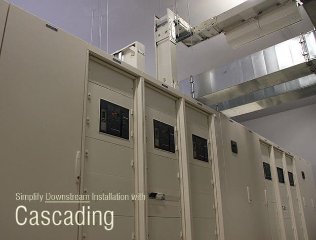
Simplify Downstream Installation with Cascading (on photo Prisma P 0,42kV switchboard with Masterpact 2500A circuit breakers and Canalis busbar systems for distribution)

Few Words About Cascading

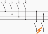
Cascading circuit breakers installation
Cascading provides circuit breakers placed downstream of a limiting circuit breaker with an enhanced breaking capacity. The limiting circuit breaker helps the circuit breaker placed downstream by limiting high short-circuit currents.

Cascading makes it possible to use a circuit-breaker with a breaking capacity lower than the short-circuit current calculated at its installation point.


Area of Cascading Application

  • Concerns all devices installed downstream of this circuit-breaker,
  • Can be extended to several consecutive devices, even if they are used in different switchboards.

The installation standards (IEC 60364) stipulate that the upstream device must have an ultimate breaking capacity Icu greater than or equal to the assumed short-circuit current at the installation point.

For downstream circuit-breakers, the ultimate breaking capacity Icu to be considered is the ultimate breaking capacity enhanced by coordination.


Implementation Techniques

Principles

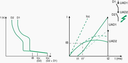
As soon as the two circuit-breakers trip (as from point IB), an arc voltage UAD1 on separation of the contacts of D1 is added to voltage UAD2 and helps, by additional limitation, circuit-breaker D2 to open.

Cascading circuit breakers tripping curves

Cascading circuit breakers tripping curves


The association D1 + D2 allows an increase in performance of D2 as shown in figure 2 below:

  • Limitation curve D2,
  • Enhanced limitation curve of D2 by D1,
  • Icu D2 enhanced by D1.

In actual fact, in compliance with the recommendations of IEC 60947-2, manufacturers give directly and guarantee Icu enhanced by the association of D1 + D2.

Cascading enhanced circuit-breakers tripping curves

Cascading enhanced circuit-breakers tripping curves


In a cascade system, both the upstream and downstream devices are expected to operate simultaneously so that the fault energy is shared by the breaking devices. Unless the combination is tested for the required fault level, the performance of the combination cannot be guaranteed in the field.

After a major fault is cleared both the devices of the combination need to be thoroughly examined and replaced if necessary to ensure safe operation during any future fault in the system.

Advantages of Cascading

Cascading allows benefit to be derived from all the advantages of limitation. Thus, the effects of short-circuit currents are reduced, i.e.:

  • Electromagnetic effects,
  • Electrodynamic effects,
  • Thermal effects.

Installation of a single limiting circuit-breaker results in considerable simplifications and savings for the entire downstream installation:

  • Simplification of choice of devices by the cascading tables,
  • Savings on downstream devices. Limitation enables circuit-breakers with standard performance to be used.

Thanks to cascading, circuit breakers with breaking capacities less than the prospective short-circuit current may be installed downstream from a current limiting circuit breaker. It follows that substantial savings can be made on downstream switchgear and enclosures.

Resource: Merlin Gerin/Schneider Electric Circuit breaker application guide

Gas-Insulated Transmission Line (GIL) System Design

$
0
0


Gas-Insulated Transmission Line (GIL) System Design

Gas-Insulated Transmission Line (GIL) System Design (on photo Tunnel-Laid GIL by SIEMENS)

Introduction to GIL

Gas Insulated Transmission Line (GIL) Construction

Gas Insulated Transmission Line (GIL) Construction


GIL systems are based on the successful SF6 tubular conductor technology, which has been around for several decades. GIL consist of a central aluminum conductor with a typical electrical cross section of up to 5,300 mm2.

The conductor rests on cast resin insulators, which center it within the outer enclosure.

This enclosure is formed by a sturdy aluminum tube, which provides a solid mechanical and electrotechnical containment for the system. To meet up-to-date environmental and technical aspects, GIL are filled with an insulating gas mixture of mainly nitrogen and a smaller percentage of SF6 gas.

GIL was developed to meet a wide variety of requirements for installation and operation. A decisive factor in meeting this demand was an installation process that permits assembly of prefabricated modules at the installation site, thus allowing optimum adoption of the selected routing.

This concept also has logistic advantages. All elements such as tubes, angles and special modules are lightweight and small enough to be transported by comparatively light standard trucks.


Technical Data

The main technical data of the GIL for 420kV and 550kV transmission networks are shown in table below.

For 550-kV applications, the SF6 content or the diameter of the enclosure pipe might be increased. The rated values shown in table below are chosen to match the requirements of the high-voltage transmission grid of overhead lines.

Table – Technical Data for 420kV and 550kV GIL Transmission Networks

TypeValue
Nominal voltage (kV)420/550
Nominal current (A)3150/4000
Lightning impulse voltage (kV)1425/1600
Switching impulse voltage (kV)1050/1200
Power frequency voltage (kV)630/750
Rated short-time current (kA=3s)63
Rated gas pressure (bar)7
Insulating gas mixture80% N2, 20% SF6

The power transmission capacity of the GIL is 2000 MVA whether tunnel laid or directly buried. This allows the GIL to continue with the maximum power of 2000 MVA of an overhead line and bring it underground without any reduction in power transmission.

The values are in accordance with the relevant IEC standard for GILs, IEC 61640.


Standard Units

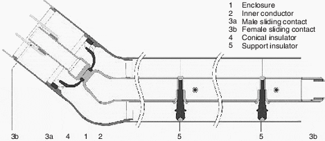
Figure 1 shows a straight unit combined with an angle unit.

The straight unit consists of a single-phase enclosure made of aluminum alloy. In the enclosure (1), the inner conductor (2) is fixed by a conical insulator (4) and lies on support insulators (5).

Straight construction unit with angle element

Figure 1 - Straight construction unit with angle element


The thermal expansion of the conductor toward the enclosure is adjusted by the sliding contact system (3a, 3b). One straight unit has a length up to 120 m made by single pipe sections welded together by orbital-welding machines.

If a directional change exceeds what the elastic bending allows, then an angle element (shown in Fig. 1) is added by orbital welding with the straight unit. The angle element covers angles from to 90°. Under normal conditions of the landscape, no angle units are needed because the elastic bending, with a bending radius of 400 m, is sufficient to follow the contour.

At distances of 1200–1500 m, disconnecting units are placed in underground shafts. Disconnecting units are used to separate gas compartments and to connect high-voltage testing equipment for the commissioning of the GIL.

The compensator unit is used to accommodate the thermal expansion of the enclosure in sections that are not buried in the earth. A compensator is a type of metallic enclosure, a mechanical soft section, which allows movement related to the thermal expansion of the enclosure. It compensates the length of thermal expansion of the enclosure section.

Thus compensators are used in tunnel-laid GILs as well as in the shafts of directly buried GILs.

The enclosure of the directly buried GIL is coated in the factory with a multilayer polymer sheath as a passive protection against corrosion. After completion of the orbital weld, a final covering for corrosion protection is applied on site to the joint area. Because the GIL is an electrically closed system, no lightning impulse voltage can strike the GIL directly.

Therefore, it is possible to reduce the lightning impulse voltage level by using surge arresters at the end of the GIL. The integrated surge-arrester concept allows reduction of high-frequency overvoltages by connecting the surge arresters to the GIL in the gas compartment.

For monitoring and control of the GIL, secondary equipment is installed to measure gas pressure and temperature. These are the same elements that are used in gas-insulated switchgear (GIS).

For commissioning, partial-discharge measurements are obtained using the sensitive very high frequency (VHF) measuring method.

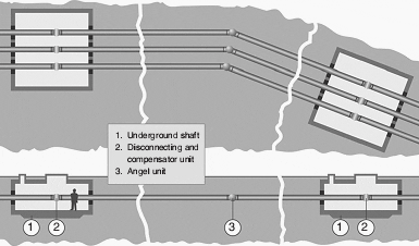
Directly buried GIL system components

Figure 2 - Directly buried GIL system components


An electrical measurement system to detect arc location is implemented at the ends of the GIL. Electrical signals are measured and, in the ver y unlikely case of an internal fault, the position can be calculated by the arc location system (ALS) wi th an accuracy of 25 m.

The third component is the compensator, installed at the enclosure. In the tunnel-laid version or in an underground shaft, the enclosure of the GIL is not fixed, so it wi ll expand in response to thermal heat-up during operation. The thermal expansion of the enclosure is compensated by the compensation unit.

If the GIL is directly buried in the soil, the compensation unit is not needed because of the weig ht of the soil and the friction of the surface of the GIL enclosure.

The fourth and last basic module used is the disconnecting unit, which is used every 1.2–1.5 km to separate the GIL in gas compartments. The disconnecting unit is also used to carr y out sectional hig h-voltage commissioning testing.

An assembly of all these elements as a typical setup is shown in Fig . 2, which illustrates a section of a GIL between two shafts (1). The underground shafts house the disconnecting and compensator units (2). The distance between the shafts is between 1200 and 1500 m and represents one single gas compartment. A directly buried angle unit (3) is shown as an example in the middle of the figure.

Each angle unit also has a fix point, where the conductor is fixed toward the enclosure.


Laying Methods

The GIL can be laid aboveground on structures, in a tunnel, or directly buried into the soil like an oil or gas pipeline. The overall cost for the directly buried version of the GIL is, in most cases, the least expensive version of GIL laying . For this laying method, sufficient space is required to provide accessibility for working on site.

Consequently, directly buried laying will generally be used in open landscape crossing the countryside, similar to overhead lines, but invisible.


Aboveground installation

Aboveground GIL

Aboveground GIL


GIL installation aboveground is a trouble-free option, even for extreme environmental conditions. GIL are unaffected by high ambient temperatures, intensive solar radiation or severe atmospheric pollution (such as dust, sand or moisture). Corrosion protection is not always necessary.

Particularly high transmission power can be achieved with aboveground installation.


Tunnel installation

GIL systems installed in a tunnel

GIL systems installed in a tunnel


Tunnels made up of prefabricated structural elements are another quick and easy method of GIL installation. The tunnel elements are assembled in a trench, which is then backfilled to prevent any long-term disfiguring of the local landscape.

The GIL is installed once the tunnel has been completed. With this method of installation the land above the tunnel can be fully restored to agricultural use. Only a negligible amount of heat is dissipated to the soil from the GIL. The system stays accessible for easy inspection and high transmission capacity is ensured.


Vertical installation

Vertical GIL

Vertical GIL


Gas-insulated tubular conductors can be installed without a problem at any gradient, even vertically. This makes them a top solution especially for cavern hydropower plants, where large amounts of energy have to be transmitted from the underground machine transformer to the switchgear and overhead line on the surface.

As GIL systems pose no fire risk, they can be installed in a tunnel or shaft that is accessible and can also be used for ventilation at the same time.


Direct burial

Direct burial GIL

Direct burial GIL


Siemens also offers GIL solutions designed for direct burial. These systems are coated with a continuous polyethylene layer to safeguard the corrosion-resistant aluminum alloy of the enclosure, providing protection of the buried system for > 40 years.

As magnetic fields are marginal in the vicinity of all Siemens GIL applications, the land can be returned to agricultural use with very minor restrictions once the system is completed.


High EM compatibility

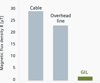
Magnetic fields in microtesla (µT) for GIL, overhead transmission line and cable (XLPE, cross-bonding) for a 400 kV double system at 2 x 1,000 MVA load, GIL and cable laid at a depth of 1 m.

Comparison of the magnetic fields

Comparison of the magnetic fields for different high-voltage transmission systems

How are Gas-Insulated Transmission Lines used?

Cant see this video? Click here to watch it on Youtube.

Resources: Siemens Gas-Insulated Transmission Line – GIL; Substation Engineering Design

Definitions of Voltage Transformer Parameters

$
0
0


Definitions of the Toltage Transformer Parameters

Definitions of the Toltage Transformer Parameters (on photo withdrawable voltage trasnformers 36kV in Schneider Electric's DNF7 AIS MV Switchgear)

VT Parameters

  1. Rated voltage factor
  2. Rated primary voltage (Up)
  3. Rated secondary voltage
  4. Accuracy power
  5. Accuracy class
  6. Voltage ratio error
  7. Phase or phase displacement error
  8. Rated thermal limiting output

Introduction to VTs

The voltage transformer must comply with the network specifications, this is essential.

As with any device, the voltage transformer must meet requirements relating to the voltage, current and frequency. Voltage transformer specifications are only valid for normal conditions of use. A derating should be provided for in accordance with the ambient temperature and the altitude.

Rated voltage factor: this is the factor by which the rated primary voltage must be multiplied in order to determine the maximum voltage for which the transformer must attain the required levels of heating and accuracy. Go to Top ↑

The voltage factor is determined by the maximum operating voltage, which depends on the network earthing system and the way the VT’s primary winding is connected.

The voltage transformer must be able to withstand this maximum voltage for the time necessary to clear the fault (see Table 1 below).


Table 1 – Normal values of the rated voltage factor

Rated voltage factorRated timePrimary winding connection methodNetwork earthing system
1.2continuousphase to phaseany
1.2continuousbetween the neutral
point of a star
transformer and earth
any
1.2continuousphase to earthdirectly earthed neutral
1.530 seconds
1.2continuousphase to earthlimiting resistance earthing
with automatic earth fault
clearance
(tripping upon first fault)
1.930 seconds
1.2continuousphase to earthearthed neutral without
automatic earth fault clearance
(no  tripping upon first fault)
1.98 hours
1.2continuousphase to earthtuned limiting reactance
(or Petersen coil) earthing
without automatic earth fault
clearance (no tripping upon
first fault)
1.98 hours

Note: smaller time ratings are permissible by agreement between manufacturer and user.


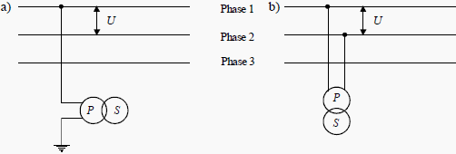
Rated primary voltage (Up): Depending on their design, voltage transformers will be connected either:

  1. Between phase and earth (see Figure 1a); or
  2. Between phases (see Figure 1b).

Rated primary voltage formulae


Voltage transformer connections

Figure 1 - Voltage transformer connections


The voltage transformer must be suited to requirements relating to protection and measuring devices.

The foreseen application of the voltage transformer is used to determine the rated secondary voltage, the accuracy power, the accuracy class and the thermal power limit.

Rated secondary voltage: this is equal to 100 or 110 V for phase/phase VTs. For single-phase transformers designed to be connected between a phase and earth, the rated secondary voltage is divided by √3. Go to Top ↑

For example:

Rated secondary voltage formulae


Accuracy power: this is expressed in VA and it is the apparent power that the voltage transformer can supply to the secondary when it is connected under its rated primary voltage and connected to its accuracyload. It must not introduce an error in excess of the values guaranteed by the accuracy class. Go to Top ↑

The standardized values are: 10 – 15 – 25 – 30 – 50 – 75 – 100 – 150 – 200 – 300 – 400 – 500 – VA.

Accuracy class: this defines the guaranteed transformation ratio and phase error limits in specified power and voltage conditions. Go to Top ↑

Voltage ratio error: this is the error that the transformer introduces in the voltage measurement:

Voltage ratio error formulae


Phase or phase displacement error: this is the phase difference between the primary and secondary voltages and is expressed in minutes. Go to Top ↑

Rated thermal limiting output: this is the apparent power that the transformer can permanently supply at its rated secondary voltage without exceeding the heating limits stipulated in the standards.
Go to Top ↑


Accuracy class

Table 2 gives the accuracy class generally used in accordance with the corresponding application.

Table 2 – Accuracy class in accordance with the application for measuring VTs

ApplicationAccuracy class
Not used in industry0.1
Precision metering0.2
Usual metering0.5
Statistical metering and/or measurement1
Measurement not requiring high accuracy3

The accuracy class is guaranteed if the voltage is between 80 and 120% of the rated primary voltage and for any load between 25 and 100% of the rated accuracy power with an inductive power factor of 0.8.

The standardized IEC accuracy classes are: 0.1 – 0.2 – 0.5 – 1 – 3.
  1. Classes 0.1 and 0.2 are only used for laboratory devices.
  2. Classes 0.5 and 1 are used in the majority of cases.
  3. Class 3 is used very little.


Resource: Protection of Electrical Networks – Christophe Prévé (get this book from Amazon)

Testing and Commissioning of Current Transformer

$
0
0


Testing and Commissioning of Current Transformer

Testing and Commissioning of Current Transformer (on photo two current transformers in MV cubicle; by alcatelmacedonia @ Flickr)

Content

1. Objective
2. Test Equipment Required
3. Test procedures

  1. Mechanical Check and Visual Inspection
  2. Insulation Resistance Test
  3. Polarity Test
  4. Secondary/Loop Resistance Test
  5. Burden Test (optional test)
  6. Magnetization Curve Test (optional test)
  7. Turns Ratio Test (optional test)
  8. Primary Injection Test
  9. High Voltage Test
  10. Commisioning Test

4. Applicable Standards
5. Live VIDEO CT Testing (6 Testings)

1. Objective

To confirm the physical condition and electrical characteristics of current transformer installed in the installation. Ensure the CT is connected to system properly in all respect (primary and secondary).


2. Test Equipment Required

Required equipment for testing:

  1. Insulation tester
  2. Polarity tester
  3. Digital low ohmmeter
  4. Current source, multimeter
  5. Variac, step-up transformer (0-2kv)
  6. Primary current injection set

Go to Content ↑


3. Test Procedures

3.1. Mechanical Check and Visual Inspection

  1. Verify nameplate ratings are in accordance with the approved drawings and specifications.
  2. Inspect for physical damage/ defects and mechanical condition.
  3. Verify correct connection of transformers with system requirements.
  4. Verify that adequate clearances exist between primary and secondary circuit wiring.
  5. Verify tightness of accessible bolted electrical connections by calibrated torque-wrench method.
  6. Verify that all required grounding and shorting connection provided.
  7. Verify all shorting blocks are in correct position, either grounding or open as required.
  8. Verify single point grounding of eachcore done properly. Grounding point shall be nearer to the CT location. However grounding shall be at relay point in case of several CT secondaries connected together like differential protection.

Go to Content ↑


3.2. Insulation Resistance Test

The voltage shall be applied between:

  1. Primary to secondary plus ground (covered during switchgear test).
  2. Secondary to primary plus ground.
  3. Secondary core to core.

Test voltage limits mentioned in table below. The ambient temperature shall be noted down during test.

Table – Test Voltage Limits

Rated voltageTest voltage
100-1000V AC/DC1000V DC
>1000 to 5000V5000V DC

Go to Content ↑


3.3. Polarity Test

Polarity test is to confirm the polarity marking on the CT primary and secondary and verify it is matching with drawing. More ever it is giving an idea, how to connect the secondaries to make the protection (like directional, differential) and metering function properly.

Isolate CT secondary from the load and make circuit connection as shown in Figure 1.

Close and open the battery switch connected on the primary. Observe the pointer is moving +ve direction, while closing and –ve direction while opening for correct polarity.

CT Polarity Test

Figure 1 - CT Polarity Test

Go to Content ↑

3.4. Secondary / Loop Resistance Test (optional test)

Secondary resistance test is to verify the CT secondary winding resistance with specified one and no discontinuity in the winding. This value can be used in other calculations.

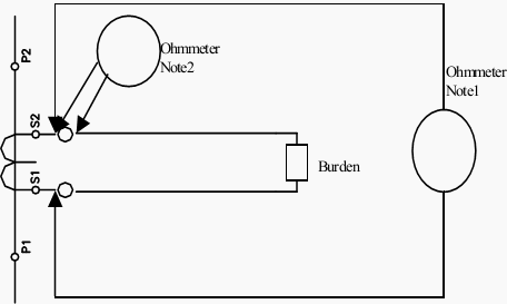
Loop resistance to ensure load is connected properly and circuits not left open. The circuit connection shall be made as shown Figure 2 for secondary resistance. Measure the dcresistance value and record. The same shall be done for all taps and cores. These values are influenced by temperature, so ambient temperature must be recorded during this test. The circuit connection shall be made as shown Figure 2 for loop resistance.

Measure the dc resistance including CT and load, phase by phase and values can be compared between them.

Limits:

The value must be with in specified on nameplate after the effect of temperature taken in to account. If not factory test results shall be taken as reference.

CT resistance / Loop Resistance Test

Figure 2 - CT resistance / Loop Resistance Test


Notes:

  • Ohmmeter connection for CT resistance excluding burden.
  • Ohmmeter connection for CT loop resistance including burden.

Go to Content ↑


3.5 Burden Test (optional test)

Burden test is to ensure the connected burden to CT is with in the rated burden, identified on the nameplate.

Injected the rated secondary current of the CT, from CT terminals towards load side by isolating the CT secondary with all connected load and observe the voltage drop across the injection points. The burden VA can be calculated as

Burden VA = Voltage drop x rated CT sec. Current.

Limits:

The calculated burden should be less than rates CT burden.

Note:

  • Ammeter selector switch should be at respective phase during test.
  • High impedance relays shall be shorted during the test.

Go to Content ↑


3.6. Magnetization Curve Test (optional test)

Magnetization Curve test is to confirm the magnetisation characteristics of CT with nameplate specification.

This test shall be conducted before ratio test and after secondary resistance and polarity test, since residual magnetism left in the core due to DC test (polarity, resistance), which leads additional error in ratio test. The meters used for this test shall be having true RMS measurement.

The circuit connection shall be made as shown Figure 3. The primary should be open during test.

Demagnetisation

Before start the test demagnetise the core by Inject voltage on secondary terminals and increase up to where considerable increment in current with small voltage increment. Now start decreasing the voltage to zero, the rate at which increased.

Magnetisation test

Now increase the voltage and monitor the excitation current up to the CT reaching near to saturation point. Record the reading of voltage and current at several points. Plot the curve and evaluate the Vk and Img from the graph.


Limits:

Class X CT:
The obtained Vk should be greater than specified one; mag current should be less than specified one.

Protection class CT:
The secondary limiting voltage can be calculated as follow:

Vslv = Is * ALF (Rct + (VA/Is*Is))

Where:
Is – rated secondary current
Rct – CT secondary resistance
VA – rated CT burden
ALF – Accuracy limit factor

The mag current (Img) drawn at Vslv can be obtained from graph. The following criteria should be satisfied.

Img < accuracy class * ALF * Is

Metering Class CT:
Accuracy can be ensured as follow:

Img at Vs (= 1.2 * VA / Is) should be less than (accuracy class * Is)

And instrument security factor to be verified.

Magnetisation Test

Figure 3 - Magnetisation Test

Go to Content ↑

3.7. Turns ratio Tests (optional test)

This test is to ensure the turn’s ratio of CT at all taps. The circuit connection shall be made as shown Figure 4. The primary current of minimum of 25% rated primary current to be injected on primary side of CT with secondaries shorted and the secondary current can be measured and recorded for all cores.

Limits:

The obtained turn’s ratio should match with rated nameplate ratio.

Go to Content ↑


3.8. Primary Injection Test

This test is to ensure the CT circuits are properly connected with respected cores and there is no mix up in the circuit (phase identification).

The circuit connections shall be made as shown in Figure 4. Single point grounding shall be verified for CT circuits, before starting this test. Inject 25% of rated primary current between one phase and earth with all connected burden. Measure secondary current at all points of CT circuits. It shall be done for other phases.

Core identification:

When one CT is having several cores used for different purposes. The cores can be identified during primary injection test by shorting the one of the core at CT terminal itself and check there isno current only at relevant load. The same can be verified for other cores.

Inject 25% of rated primary current between phase to phase with all connected burden. Measure secondary current at all points of CT circuits. It shall be done for other phases.

Limits:

  • Secondary current should only be observed at respective phase and neutral leads during Phase to earth injection.
  • Secondary current should only be observed at respective phases and no current on neutral during Phase to phase injection.
Primary injection / Ratio test

Figure 4 - Primary injection / Ratio test

Go to Content ↑

3.9. High Voltage Test

This test is included with switchgear high voltage.

Objective of HV test is to determine the equipment is in propercondition to put in service, after installation for which it was designed and to give some basis for predicting whether or not that a healthy condition will remain or if deterioration is underway which can result in abnormally short life.

Test Instruments Required for HV Test

Calibrated AC hi-pot test set for switchgear with leakage current indicator and overload protection. Calibrated DC hi-pot test set for cables with leakage current indicator and overload protection.

Go to Content ↑


3.10. Commisioning Test

After commissioning, secondary current measurement shall be carried out in CT circuits. Phase angle check shall be done for correct direction. Go to Content ↑


4. Applicable Standards

  • IEC 60044-1: Instrument transformers – current transformer.
  • IEC 60694: common specifications for HV switchgear.

Go to Content ↑


5. Live VIDEO CT Testing (6 Testings)

1. CT Tests – Ratio and Polarity

Cant see this video? Click here to watch it on Youtube.


2. CT Tests – Burden Secondary Side

Cant see this video? Click here to watch it on Youtube.


3. CT Tests – Excitation Curve

Cant see this video? Click here to watch it on Youtube.


4. CT Tests – Winding or Burden Resistance

Cant see this video? Click here to watch it on Youtube.


5. CT Tests – Voltage Withstand Test

Cant see this video? Click here to watch it on Youtube.


6. CT Tests – Polarity By Pulses

Cant see this video? Click here to watch it on Youtube.


Resource: Testing and Commissioning of Electrical Equipment – Schneider Electric Service Dpt.


Few Words About Three-Phase Alternator

$
0
0


Few Words About Three-Phase Alternator

Few Words About Three-Phase Alternator

Introduction

The three-phase alternator, as the name implies, has three single-phase windings spaced such that the voltage induced in any one phase is displaced by 120º from the other two. A schematic diagram of a three-phase stator showing all the coils becomes complex, and it is difficult to see what is actually happening.

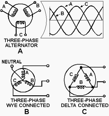
The simplified schematic of figure 1, view A, shows all the windings of each phase lumped together as one winding.

The rotor is omitted for simplicity. The voltage waveforms generated across each phase are drawn on a graph, phase-displaced 120º from each other. The three-phase alternator as shown in this schematic is made up of three single-phase alternators whose generated voltages are out of phase by 120º.

The three phases are independent of each other.

Three-phase alternator connections

Figure 1 - Three-phase alternator connections

Rather than having six leads coming out of the three-phase alternator, the same leads from each phase may be connected together to form a wye (Y) connection, as shown in Figure 1, view B.

It is called a wye connection because, without the neutral, the windings appear as the letter Y, in this case sideways or upside down.

The neutral connection is brought out to a terminal when a single-phase load must be supplied. Single-phase voltage is available from neutral to A, neutral to B, and neutral to C. In a three-phase, Y-connected alternator, the total voltage, or line voltage, across any two of the three line leads is the vector sum of the individual phase voltages. Each line voltage is 1.73 times one of the phase voltages.

Because the windings form only one path for current flow between phases, the line and phase currents are the same (equal). A three-phase stator can also be connected so that the phases are connected end-to-end; it is now delta connected (fig. 1, view C). (Delta because it looks like the Greek letter delta, ∆.)

In the delta connection, line voltages are equal to phase voltages, but each line current is equal to 1.73 times the phase current. Both the wye and the delta connections are used in alternators.

The majority of all alternators in use today are three-phase machines. They are much more efficient than either two-phase or single-phase alternators.

Three-Phase Connections

The stator coils of three-phase alternators may be joined together in either wye or delta connections, as shown in Figure 2. With these connections only three wires come out of the alternator. This allows convenient connection to three-phase motors or power distribution transformers.

It is necessary to use three-phase transformers or their electrical equivalent with this type of system.

Three-phase alternator or transformer connections

Figure 2 - Three-phase alternator or transformer connections


A three-phase transformer may be made up of three, single-phase transformers connected in deltawye, or a combination of both. If both the primary and secondary are connected in wye, the transformer is called a wye-wye.

If both windings are connected in delta, the transformer is called a delta-delta. Figure 3 shows single-phase transformers connected delta-delta for operation in a three-phase system. You will note that the transformer windings are not angled to illustrate the typical delta (∆) as has been done with alternator windings.

Physically, each transformer in the diagram stands alone. There is no angular relationship between the windings of the individual transformers.

However, if you follow the connections, you will see that they form an electrical delta. The primary windings, for example, are connected to each other to form a closed loop. Each of these junctions is fed with a phase voltage from a three-phase alternator.

The alternator may be connected either delta or wye depending on load and voltage requirements, and the design of the system.

Three single-phase transformers connected delta-delta

Figure 3 - Three single-phase transformers connected delta-delta


Figure 4 shows three single-phase transformers connected wye-wye. Again, note that the transformer windings are not angled. Electrically, a Y is formed by the connections. The lower connections of each winding are shorted together. These form the common point of the wye.

The opposite end of each winding is isolated. These ends form the arms of the wye.

Three single-phase transformers connected wye-wye

Figure 4 - Three single-phase transformers connected wye-wye


The ac power on most ships is distributed by a three-phase, three-wire, 450-volt system. The single-phase transformers step the voltage down to 117 volts. These transformers are connected delta-delta as in figure 3.

With a delta-delta configuration, the load may be a three-phase device connected to all phases; or, it may be a single-phase device connected to only one phase.

At this point, it is important to remember that such a distribution system includes everything between the alternator and the load. Because of the many choices that three-phase systems provide, care must be taken to ensure that any change of connections does not provide the load with the wrong voltage or the wrong phase.


Output Frequency

The output frequency of alternator voltage depends upon the speed of rotation of the rotor and the number of poles. The faster the speed, the higher the frequency. The lower the speed, the lower the frequency.

The more poles there are on the rotor, the higher the frequency is for a given speed. When a rotor has rotated through an angle such that two adjacent rotor poles (a north and a south pole) have passed one winding, the voltage induced in that winding will have varied through one complete cycle. For a given frequency, the more pairs of poles there are, the lower the speed of rotation.

This principle is illustrated in figure 5; a two-pole generator must rotate at four times the speed of an eight-pole generator to produce the same frequency of generated voltage.

Frequency regulation

Figure 5 - Frequency regulation


The frequency of any ac generator in hertz (Hz), which is the number of cycles per second, is related to the number of poles and the speed of rotation, as expressed by the equation:

F = NP / 120

where P is the number of poles, N is the speed of rotation in revolutions per minute (rpm), and 120 is a constant to allow for the conversion of minutes to seconds and from poles to pairs of poles.

Examples

For example, a 2-pole, 3600-rpm alternator has a frequency of 60 Hz; determined as follows:

(2 x 3600) / 120 = 60 HZ

A 4-pole, 1800-rpm generator also has a frequency of 60 Hz. A 6-pole, 500-rpm generator has a frequency of:

(6 x 500) / 120 = 25 Hz

A 12-pole, 4000-rpm generator has a frequency of:

(12 x 4000) / 120 = 400 Hz

Resource: Introduction to motor and generator - Navy Electricity and Electronics Training Series

Cable Engineering in Substation and Power Plant

$
0
0


Cable Engineering in Substation and Power Plant

Cable Engineering in Substation and Power Plant (on photo: Sealing of power cables through the outer wall in substation; by Roxtec Ltd. @ Flickr)

Single core cable should be unarmored?

Is it true that single core cable should be unarmored because eddy currents are induced in armor of single core cable which will cause additional losses? If true then why not three core cables also unarmored and why single core armored cables manufactured at all.

In this scenario one phase induces eddy current in the armor and in three phases it is not there as the flux of all the three phases cancel each other so armoring is required what is the solution, we can use non Ferromagnetic substance for armoring.

A detailed description is given below:

1. Aluminium Wire Armor (AWA) and Galvanized Steel Wire (GSW) are offered as standard mechanical protection for single and three core cables respectively.

2. Non ferromagnetic materials must be used on single core cables. As the magnetic field travels through any protection layers on single core cables, a ferromagnetic material such as steel will have significant eddy current losses induced in the wires causing significant heating of the cable and subsequent derating of its current carrying capacity.

The same principle applies when selecting cable clamps.

3. Even if a single core cable is armored with ferromagnetic material like steel then three single core cable has to be laid in trefoil arrangement so that the flux of all the three single core cable cancel each other as happens in three core cable.


What type of armor should be used, wire or strip armor and when?

As per bureau of Indian standards no 7098 part-2 clause 16.2 Type of Armor – Where the calculated diameter below armoring does not exceed 13 mm, the armor shall consist of galvanized round steel wires.

The armor of cables having calculated diameter below armoring greater than 13 mm shall consist of either galvanized round steel wires or galvanized steel strips.


What are the required conditions for earthed system?

Earthed System – An electric system which fulfils any of the following conditions:

1. Neutral point or the mid-point connection is earthed in such a manner that, even under fault conditions, the maximum voltage that can occur between any conductor and the earth does not exceed 80 percent of the nominal system voltage.

2. The neutral-point or the mid-point connection is not earthed but a protective device is installed which automatically cuts out any part of the system which accidently becomes earthed.

3. In case of ac systems only, the neutral-point is earthed through an arc suppression coil with arrangement for isolation within 1 h of occurrence of the fault for the non-radial field cables and within 8 hours for radial cables, provided that the total of such periods in a year does not exceed 125 hours.


What are the required conditions for unearthed system?

An electric system which does not fulfill the requirement of the earthed system is unearthed system.


What is meant by earth grade of cables?

Earth grade of a cable is parameter which governs the degree of sufficient separation between the conductor and the nearest electrical ground to preclude dielectric failure and makes sure that the required thickness of insulation, to physically protect the conductor, is more than adequate for required dielectric strength.

For cables to be used in solidly earthed system, the phase conductor to armor insulation has to be rated for VL/√3 volts that is phase to ground voltage only. This earth grade is to be adopted when the system is solidly earthed without any intentional resistance or inductance in neutral circuit.

In case the system is resistance/inductance earthed or unearthed, the phase to ground voltage of two healthy phases rises to approximately phase to phase voltage when earth fault occurs in the third phase.

The phase to ground voltage of healthy phase comes very close to or attains phase to phase value depending upon the degree of effectiveness of system neutral earthing. Hence phase conductor to armor insulation of cables used in unearthed or resistance/inductance earthed system should be rated for full phase to phase voltage instead of VL/√3.

For example in case of 6.6kV unearthed or resistance earthed system 6.6kV/6.6kV UE class cables should be used while 6.6kV/3.85kV E class cables are adequate for solidly earthed system.

So insulation class of cables of any particular voltage level for unearthed system is equivalent to insulation class of next voltage level of earthed system.

So now question is for 6.6kV resistance earthed system can we use 11kV/6.35kV E class cables?

Since for the selected cable phase to phase voltage is 11kV and phase to ground voltage is 11kV/√3=6.35kV, which is lesser than the phase to phase voltage of 6.6kV system and hence during earth fault in one phase the insulation of healthy phase may prove to be insufficient.

AS PER IS-IS 7098, Indian Standard Specification for cross linked polyethylene insulated PVC sheathed cables part-2 for working voltage from 3.3kV up to and including 33kV (7098 part-2) gives the following clause for the same:-

The standard covers the requirements of following categories of cross linked polyethylene insulated and PVC sheathed power cables for single phase or three phase (earthed or unearthed) systems for electricity supply purposes:

a) Types of Cables

  1. Single-core unscreened, unarmored (but – non-magnetic metallic tape covered)
  2. Single-core screened, unarmored
  3. Single-core armored (non-magnetic) screened or unscreened
  4. Three-core armored, screened or unscreened

b) Voltage Grade (UO/U)

  1. Earthed System – 1.9/3.3 kV, 3.8/6.6 kV, 6.35/11 kV, 12.7/22 kV and 19/33 kV
  2. Unearthed System – 3.3/3.3 kV and 11/11 kV
NOTES:
  • Cables of 6.35/11 kV grade (earthed system) are suitable for use on 6.6/6.6 kV (unearthed system) also.
  • The cables conforming to this standard may be operated continuously at a power frequency voltage 10 percent higher than rated voltage.
  • Under Rule 54 of the Indian Electricity Rules 1956, in case of high voltage, the permissible variation of declared voltage at the point of commencement of supply is +6 & -9 percent.

How many types of cable faults are there & how are they diagnosed?

Faults can be divided into two types:

  1. Series type cable fault
  2. Shunt type cable fault

1. Series type cable faults

Series fault occur where the continuity one or more of metallic element (i.e. conductor or sheath) of cable is impaired. Usually series faults only become apparent when continuity has been completely lost at least in one conductor, to cause an open circuit fault.


2. Shunt type cable faults

Shunt fault occur where the insulation of one or more conductor is damaged. The most common type of shunt fault is single phase to earth fault. On screened cables, all shunt faults are earth faults.

Depending on the degree of carbonization of the dielectric, the shunt fault could be of following types:

  1. High Resistance fault
  2. Low Resistance fault
  3. Flashing fault

Diagnosis:

Usually the first indication of the possible existence of a fault is given by the automatic operation of the circuit protection. The faulty cable should be disconnected from the other electrical equipments and is retested for confirmation of fault in insulation by applying D.C. High voltage or by Megger.

If the insulation indicates a “healthy” result, cable continuity should be checked.

In case the insulation shows a faulty cable, the value of fault resistance should be measured with a multimeter.

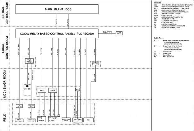
Facts about interface cabling between control & instrumentation and electrical for any power plant or process plant.

Regarding C&I cables for any power or process plants, please note that there are two categories of cables:

  1. Those C&I cables which are to be considered by electrical group. They are mainly control/indication/annunciation related cables.
  2. Those C&I cables which are to be considered by Instrumentation group.

The C&I cable supposed to be considered by electrical group:

  1. Special cables for interface between PLC/Relay based control panel (in local control room to) and main plant DCS or ECP. In most cases nature of such cables is Fiber optics because of large amount of data to be carried over a large distance.
  2. Cables between PLC and MCC for analog and binary signals. Nature of such cables is usually paired cables, which may be twisted or untwisted pair. Engineering including scheduling with terminal details and interconnection diagram, procurement and erection of above mentioned two types of C&I cables is carried out by electrical group.

The C&I cables supposed to be considered by Instrumentation group and consequently excluded by electrical group:

  1. Paired cable from PLC to instrument JB in the local instrument rack or enclosure in the field.
  2. Paired cables between Instrument JB in the local instrument rack or enclosure to field instruments.
  3. Paired cable between PLC & packaged vendor panels like VMS (Vibration monitoring system), IPR & SOV.
  4. Paired cable between above mentioned packaged vendor panels to Junction box in field.
  5. Special cables between field junction box to individual instruments by packaged vendors like vibration sensors.
  6. Paired cable between PLC to modulating drives.
  7. Paired cable between bidirectional drive to PLC.
  8. Cables between GPS clock system (for time synchronization) and PLC/SCADA. Please note that the target of such time synchronization of DCS or PLCs (located geographically apart) with GPS is that, if we have more than one controller system, by default each system will have its clock adjusted individually from the PC which downloaded the program in the system, so if any trip or trouble occur in the system and all the system doesn’t have the same time, the reports will be messy and confused about at which time the problem occur due to difference in reporting time.
    .
    So a main controller or GPS signal is send to every control system in a specified time so that every system readjusts its clock and has same time in terms of hour minute and seconds.

Summary

Cables mentioned in point number-II are the only two types of instrumentation cable which electrical group considers and engineering done thereby requires interface & coordination with C&I department.

Eight types of cables mentioned in point number-III, should not be considered by electrical group of any project. These cables are exclusively C&I cables and entire engineering & procurement is to be carried out by C&I department.

Erection is sometimes carried out by electrical contractor, but in most cases erection is carried out by C&I site team on perforated type cable trays dedicated for instrumentation.


Cable Block Diagram

Download cable block diagram in PDF.

Cable Block Diagram

Cable Block Diagram


The Good, The Bad and The Ugly Cable Insulation

$
0
0


The Good, The Bad and The Ugly Cable Insulation

The Good, The Bad and The Ugly Cable Insulation

Insulation Fundamentals

The fundamental understanding of cable insulation properties forms the foundation for assessment of cable operability.

These same fundamentals provide the basis for evaluating whether various electrical and physical tests and measurements are meaningful, cost-effective, and warranted, and are a basis for evaluation of present or conventional cable test practices against the critical properties of concern for:

  • Cable operability
  • Life extension
  • Retention of the original environmental qualification, and
  • The adequacy of environmental qualification.

General Properties of Insulation

The electrical properties of concern for cable insulations are dielectric loss properties (resistivity, insulation resistance, dielectric constant and permittivity) and dielectric endurance properties (dielectric strength, breakdown strength, and ability to withstand corona attack).

Although these properties are important for higher voltage and other specialty applications, many of them lose their importance for the low-voltage cabling used in thermal/nuclear power plants.

It is demonstrated that the significance of mechanical and thermal properties depend upon the application of the cable.

Insulation resistance measurements are commonly used to evaluate insulation systems.

For shielded cable, insulation resistance is directly related to the volume resistivity of the cable.

For unshielded cable, the insulation resistance has a complex relationship to volume and surface resistivity because there is no shield for a return path.


Good Cable Insulation

When voltage is impressed across any insulation system, some current leaks into, through, and around the insulation. When testing with DC high-voltage, capacitive charging current, insulation absorption current, insulation leakage current, and by-pass current are all present to some degree.

For the purposes of this article on cable fault locating, only leakage current through the insulation will be considered.

For shielded cable, insulation is used to limit current leakage between the phase conductor and ground or between two conductors of differing potential. As long as the leakage current does not exceed a specific design limit, the cable is judged good and is able to deliver electrical energy to a load efficiently.

Cable insulation may be considered good when leakage current is negligible but since there is no perfect insulator even good insulation allows some small amount of leakage current measured in microamperes.

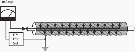
See Figure 1.

Cable Good insulation

Figure 1 - Cable Good insulation


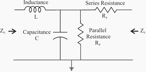
The electrical equivalent circuit of a good run of cable is shown in Figure 2. If the insulation were perfect, the parallel resistance RPwould not exist and the insulation would appear as strictly capacitance. Since no insulation is perfect, the parallel or insulation resistance exists.

This is the resistance measured during a test using a Megger Insulation Tester.

Current flowing through this resistance is measured when performing a DC Hipot Test as shown in Figure 1.

The combined inductance (L), series resistance (RS), capacitance (C) and parallel resistance (RP) as shown in Figure 2 is defined as the characteristic impedance (Z0) of the cable.

When Cable Insulation Is Bad?

When the magnitude of the leakage current exceeds the design limit, the cable will no longer deliver energy efficiently. See Figure 3.


Why A Cable Becomes Bad?

Damaged underground electrical cable

Damaged underground electrical cable


All insulation deteriorates naturally with age, especially when exposed to elevated temperature due to high loading and even when it is not physically damaged. In this case, there is a distributed flow of leakage current during a test or while energized.

Many substances such as water, oil and chemicals can contaminate and shorten the life of insulation and cause serious problems.

Cross-linked polyethylene (XLPE) insulation is subject to a condition termed treeing. It has been found that the presence of moisture containing contaminants, irregular surfaces or protrusions into the insulation plus electrical stress provides the proper environment for inception and growth of these trees within the polyethylene material.

Testing indicates that the AC breakdown strength of these treed cables is dramatically reduced. Damage caused by lightning, fire, or overheating may require replacement of the cable to restore service.

Equivalent circuit of good cable

Figure 2 - Equivalent circuit of good cable

Cable Bad Insulation

Figure 3 - Cable bad insulation

Cable Faults Described

When at some local point in a cable, insulation has deteriorated to a degree that a breakdown occurs allowing a surge of current to ground, the cable is referred to as a faulted cable and the position of maximum leakage may be considered a catastrophic insulation failure.

See Figure 4.

Ground or shunt fault on the cable

Figure 4 - Ground or shunt fault on the cable


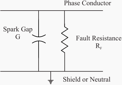
At this location the insulation or parallel resistance has been drastically reduced and a spark gap has developed. See Figure 5.

Fault region simplified diagram

Figure 5 - Fault region simplified diagram

Occasionally a series fault shown in Figure 6 can develop due to a blown open phase conductor caused by high fault current, a dig-in or a failed splice.

Open or series fault on the cable

Figure 6 - Open or series fault on the cable

The Ugly Cable Insulation

In the matter of fact, there is no ugly cable insulation. It can be either good or bad. Every condition between is considered as bad.


Hipot Cable Testing Part-1 (VIDEO)

Cant see this video? Click here to watch it on Youtube.


Hipot Cable Testing Part-2 (VIDEO)

Cant see this video? Click here to watch it on Youtube.

Resources: Power Plant Practices to Ensure Cable Operability – Electric Power Research Institute; Fault Finding Solutions – Megger

Safety Clearance Recommendations for Transformer

$
0
0


Safety Clearance Recommendations for Transformer

Safety Clearance Recommendations for Transformer (on photo 10/0.4 kV transformer substation by FIMA)

Clearance Tables

  1. Clearance from Outdoor Liquid Insulated Transformers to Buildings (NEC)
  2. Clearance between Two Outdoor Liquid Insulated Transformers (NEC)
  3. Dry Type Transformer in Indoor Installation (NES 420.21)
  4. Dry Type Transformer in Outdoor Installation (NES 420.22)
  5. Non Flammable Liquid-Insulated Transformer in Indoor Installation (NES 420.21)
  6. Oil Insulated Transformer in Indoor Installation (NES 420.25)
  7. Transformer Clearance from Building (IEEE Stand.)
  8. Transformer Clearance Specifications (Stand. Georgia Power Company)
  9. Clearance of Transformer-Cable-Overhead Line (Stand. Georgia Power Company)

Clearance from Outdoor Liquid Insulated Transformers to Buildings (NEC)

LiquidLiquid Volume (m3)Fire Resistant Wall Non-Combustible WallCombustible WallVertical Distance
Less FlammableNA0.9 Meter0.9 Meter0.9 Meter0.9 Meter
<38 m31.5 Meter1.5 Meter7.6 Meter7.6 Meter
>38 m34.6 Meter4.6 Meter15.2 Meter15.2 Meter
Mineral Oil<1.9 m31.5 Meter4.6 Meter7.6 Meter7.6 Meter
1.9 m3 to 19 m34.6 Meter7.6 Meter15.2 Meter15.2 Meter
> 19 m37.6 Meter15.2 Meter30.5 Meter30.5 Meter

Go to Content ↑

Clearance between Two Outdoor Liquid Insulated Transformers (NEC)

LiquidLiquid Volume (m3)Distance
Less FlammableNA0.9 Meter
<38 m31.5 Meter
>38 m37.6 Meter
Mineral Oil<1.9 m31.5 Meter
1.9 m3 to 19 m37.6 Meter
> 19 m315.2 Meter

Go to Content ↑

Dry Type Transformer in Indoor Installation (NES 420.21)

VoltageDistance (min)
Up to 112.5 KVA300 mm (12 in.) from combustible material unless separated from the combustible material by a heat-insulated barrier.
Above 112.5 KVAInstalled in a transformer room of fire-resistant construction.
Above 112.5 KVA with Class 155 Insulationseparated from  a fire-resistant barrier not less than 1.83 m (6 ft) horizontally and 3.7 m (12 ft) vertically

Go to Content ↑

Dry Type Transformer in Outdoor Installation (NES 420.22)

VoltageDistance (min)
Above 112.5 KVA with Class 155 Insulationseparated from  a fire-resistant barrier not less than 1.83 m (6 ft) horizontally and 3.7 m (12 ft) vertically

Go to Content ↑

Non Flammable Liquid-Insulated Transformer in Indoor Installation (NES 420.21)

VoltageDistance (min)
Over 35KVInstalled indoors Vault (Having liquid confinement area and a pressure-relief vent for absorbing any gases generated by arcing inside the tank, the pressure-relief vent shall be connected to a chimney or flue that will carry such gases to an environmentally safe area
Above 112.5 KVAInstalled in a transformer room of fire-resistant construction.
Above 112.5 KVA (Class 155 Insulation)separated from a fire-resistant barrier not less than 1.83 m (6 ft) horizontally and 3.7 m (12 ft) vertically

Go to Content ↑

Oil Insulated Transformer in Indoor Installation (NES 420.25)

VoltageDistance (min)
Up to 112.5 KVAInstalled indoors Vault (With construction of reinforced concrete that is not less than 100 mm (4 in.) thick.
Up to 10 KVA & Up to 600VVault shall not be required if suitable arrangements are made to prevent a transformer oil fire from igniting
Up to 75 KVA & Up to 600VVault shall not be required if where the surrounding Structure is classified as fire-resistant construction.
Furnace transformers (Up to 75 kVA)Installed without a vault in a building or room of fire resistant construction

Go to Content ↑

Transformer Clearance from Building (IEEE Stand)

TransformerDistance from Building (min)
Up to 75 KVA3.0 Meter
75 KVA to 333 KVA6.0 Meter
More than 333 KVA9.0 Meter

Go to Content ↑

Transformer Clearance Specifications (Stand: Georgia Power Company)

Description of ClearanceDistance (min)
Clearance in front of the transformer3.0 Meter
Between Two pad mounted transformers (including Cooling fin)2.1  Meter
Between Transformer and Trees, shrubs, vegetation( for unrestricted natural cooling )3.0 Meter
The edge of the concrete transformer pad to nearest the building4.2 Meter
The edge of the concrete transformer pad to nearest  building wall, windows, or other openings3.0 Meter
Clearance from the transformer to edge of (or Canopy) building (3 or less stories)3.0 Meter
Clearance in front of the transformer doors and on the left side of the transformer, looking at it from the front (For operation of protective and switching devices on the unit)3.0 Meter
Gas service meter relief vents.0.9 Meter
Fire sprinkler values, standpipes and fire hydrants1.8 Meter
The water’s edge of a swimming pool or any body of water.4.5 Meter
Facilities used to dispense hazardous liquids or gases6.0 Meter
Facilities used to store hazardous liquids or gases3.0 Meter
Clear vehicle passageway at all times, immediately adjacent of Transformer3.6 Meter
Fire safety clearances can be reduced by building a suitable masonry fire barrier wall (2.7 Meter wide and 4.5 Meter Tall) 0.9 Meter from the back or side of the Pad Mounted Transformer  to the side of the combustible wall
Front of the transformer must face away from the building.

Go to Content ↑

Clearance of Transformer-Cable-Overhead Line (Stand: Georgia Power Company)

Description of ClearanceHorizontal Distance (mm)
to pad-mounted transformersto buried HV cableto overhead HV Line
Fuel tanks7.5 Meter1.5 Meter7.5 Meter
Granaries6.0 Meter0.6 Meter15 Meter
Homes6.0 Meter0.6 Meter15 Meter
Barns, sheds, garages6.0 Meter0.6 Meter15 Meter
Water wells1.5 Meter1.5 Meter15 Meter
Antennas3.0 Meter0.6 MeterHeight of Antenna + 3.0 Meter

Go to Content ↑

Corrosion Types Encountered With Power Cables

$
0
0


Corrosion Types Encountered With Power Cables

Corrosion Types Encountered With Power Cables


Content

  1. Introduction
  2. Anodic Corrosion (Stray DC Currents)
  3. Cathodic Corrosion
  4. Galvanic Corrosion
  5. Chemical Corrosion
  6. AC Corrosion
  7. Local Cell Corrosion
  8. Other Forms of Corrosion

Introduction

There are numerous types of corrosion, but the ones that are discussed here are the ones that are most likely to be encountered with underground power cable facilities.

In this initial explanation, lead will be used as the referenced metal. Copper neutral wire corrosion is not discussed here.

Go to Content ↑


Anodic Corrosion (Stray DC Currents)

Stray DC currents come from sources such as welding operations, flows between two other structures, and –in the days gone by — street railway systems.

Anodic corrosion is due to the transfer of direct current from the corroding facility to the surrounding medium, usually earth. At the point of corrosion, the voltage is always positive on the corroding facility.

In the example of lead sheath corrosion, the lead provides a low resistance path for the DC current to get back to its source. At some area remote from the point where the current enters the lead, but near the inception point of that stray current, the current leaves the lead sheath and is again picked up in the normal DC return path.

The point of entry of the stray current usually does not result in lead corrosion, but the point of exit is frequently a corrosion site.

Clean sided corroded pits are usually the result of anodic corrosion. The products of anodic corrosion such as oxides, chlorides, or sulfates of lead are camed away by the current flow. If any corrosion products are found, they are usually lead chloride or lead sulfate that was created by the positive sheath potential that attracts the chloride and sulfate ions in the earth to the lead.

In severe anodic cases, lead peroxide may be formed. Chlorides, sulfates, and carbonates of lead are white, while lead peroxide is chocolate brown.

Go to Content ↑


Cathodic Corrosion

Corrosion of Metal

Corrosion of Metal - Indicative of current movement between Anodic and Cathodic Areas through the Electrolyte. The more conductive the Electrolyte, the higher rate of current movement and more accelerated the rate of corrosion.

Cathodic corrosion is encountered less fiequently than anodic corrosion, especially with the elimination of most street railway systems.

This form of corrosion is usually the result of the presence of an alkali or alkali salt in the earth. If the potential of the metal exceeds -0.3 volts, cathodic corrosion may be expected in those areas.

In cathodic corrosion, the metal is not removed directly by the electric current, but it may be dissolved by the secondary action of the alkali that is produced by the current. Hydrogen ions are attracted to the metal, lose their charge, and are liberated as hydrogen gas.

This results in a decrease in the hydrogen ion concentration and the solution becomes alkaline. The final corrosion product formed by lead in cathodic conditions is usually lead monoxide and lead / sodium carbonate. The lead monoxide formed in this manner has a bright orange / red color and is an indication of cathodic corrosion of lead.

Go to Content ↑


Galvanic Corrosion

Galvanic corrosion occurs when two dissimilar metals in an electrolyte have a metallic tie between them.

One metal becomes the anode and the other the cathode. The anode corrodes and protects the cathode as current flows in the electrolyte between them. The lead sheath of a cable may become either the anode or the cathode of a galvanic cell.

This can happen because the lead sheath is grounded to a metallic structure made of a dissimilar metal and generally has considerable length.

Copper ground rods are frequently a source of the other metal in the galvanic cell. The corrosive force of a galvanic cell is dependent on the metals making up the electrodes and the resistance of the electrolyte in which they exist. This type of corrosion can often be anticipated and avoided by keeping a close watch on construction practices and eliminating installations having different metals connected together in the earth or other electrolyte.

Go to Content ↑


Chemical Corrosion

Chemical corrosion is damage that can be attributed entirely to chemical attack without the additional effect of electron transfer.

The type of chemicals that can disintegrate lead are usually strong concentrations of alkali or acid.

Examples include alkaline solutions from incompletely cured concrete, acetic acid from volatilized wood or jute, waste products from industrial plants, or water with a large amount of dissolved oxygen.

Go to Content ↑


AC Corrosion

Until about 1970, AC corrosion was felt to be an insigruficant, but possible, cause of cable damage.

In 1907, Hayden reporting on tests with lead electrodes, showed that the corrosive effect of small AC currents was less than 0.5 percent as compared with the effects of equal DC currents. Later work using higher densities of AC current has shown that AC corrosion can be a major factor in concentric neutral corrosion.

Go to Content ↑


Local Cell Corrosion

Local cell corrosion, also known as differential aeration in a specific form, is caused by electrolytic cells that are created by an inhomogenious environment where the cable is installed.

Examples include variations in the concentration of the electrolyte through which the cable passes, variations in the impurities of the metal, or a wide range of grain sizes in the backfill. These concentration cells corrode the metal in areas of low ion concentration.

Differential aeration is a specific form of local cell corrosion where one area of the metal has a reduced oxygen supply as compared with nearby sections that are exposed to normal quantities of oxygen.

The low oxygen area is anodic to the higher oxygen area and an electron flow occurs through the covered (oxygen starved) material to the exposed area (normal oxygen level).

Differential aeration corrosion is common for underground cables, but the rate of corrosion is generally rather slow. Examples of situations that can cause this form of corrosion include a section of bare sheath or neutral wires that are laying in a wet or muddy duct or where there are low points in the duct run that can hold water for some distance.

A cable that is installed in a duct and then the cable goes into a direct buried portion is another good example of a possible differential aeration corrosion condition.

Differential aeration corrosion turns copper a bright green.

Go to Content ↑


Other Forms of Corrosion

There are numerous other forms of corrosion that are possible, but the most probable causes have been presented. An example of another form of corrosion is microbiological action of anaerobic bacteria which can exist in oxygen-fiee environments with pH values between 5.5 and 9.0.

The life cycle of anaerobic bacteria depends on the reduction of sulfate materials rather than on the consumption of free oxygen. Corrosion resulting fiom anaerobic bacteria produces sulfides of calcium or hydrogen and may be accompanied by a strong odor of hydrogen sulfide and a build-up of a black slime.

This type of corrosion is more harmful to steel pipes and manhole hardware than to lead sheaths.

Go to Content ↑

Resource: Electrical Power Cable Engineering – William A. Thue

Industrial Applications of Brushless Servomotor

$
0
0


Industrial Applications of Brushless Servomotor

Industrial Applications of Brushless Servomotor (on photo Hudson family of Brushless DC Servo Motors by Teknic)

Introduction

A synchronous machine with permanent magnets on the rotor is the heart of the modern brushless servomotor drive.

The motor stays in synchronism with the frequency of supply, though there is a limit to the maximum torque which can be developed before the rotor is forced out of synchronism, pull-out torque being typically between 1.5 and 4 times the continuously rated torque.

The torque–speed curve is therefore simply a vertical line.

The industrial application of brushless servomotors has grown significantly for the following reasons:

  • Reduction of price of power conversion products
  • Establishment of advanced control of PWM inverters
  • Development of new, more powerful and easier to use permanent magnet materials
  • The developing need for highly accurate position control
  • The manufacture of all these components in a very compact form

They are, in principle, easy to control because the torque is generated in proportion to the current. In addition, they have high efficiency, and high dynamic responses can be achieved.

Brushless servomotors are often called brushless DC servomotors because their structure is different from that of DC servomotors. They rectify current by means of transistor switching within the associated drive or amplifier, instead of a commutator as used in dc servomotors.

Confusingly, they are also called AC servomotors because brushless servo-motors of the synchronous type (with a permanent magnet rotor) detect the position of the rotational magnetic field to control the three-phase current of the armature.

It is now widely recognized that brushless ac refers to a motor with a sinusoidal stator winding distribution which is designed for use on a sinusoidal or PWM inverter supply voltage.

Brushless DC refers to a motor with a trapezoidal stator winding distribution which is designed for use on a square wave or block commutation inverter supply voltage. The brushless servomotor lacks the commutator of the DC motor, and has a device (the drive, sometimes referred to as the amplifier) for making the current flow accord-ing to the rotor position.

In the dc motor, increasing the number of commutator seg-ments reduces torque variation. In the brushless motor, torque variation is reduced by making the coil three-phase and, in the steady state, by controlling the current of each phase into a sine wave.


Application Examples (Parker Hannifin Corporation)

  1. Feed-to-length:
  • Indexing/Conveyor: Rotary Indexer
  • Following: Labelling Machine
  • Metering/Dispensing: Capsule Filling Machine
  • Flying Cutoff: Rotating Tube Cutting

  • 1. Feed-to-length

    Applications in which a continuous web, strip, or strand of material is being indexed to length, most often with pinch rolls or some sort of gripping arrangement.

    The index stops and some process occurs (cutting, stamping, punching, labeling, etc.).

    BBQ Grill-Making Machine

    Application Type: Feed-to-Length
    Motion: Linear
    Application Description: A manufactuer was using a servo motor to feed material into a machine to create barbeque grills, shopping carts, etc. The process involves cutting steel rods and welding the rods in various configurations. However, feed-length was inconsistent because slippage between the drive roller and the material was too frequent. Knurled nip-rolls could not be used because they would damage the material.

    The machine builder needed a more accurate method of cutting the material at uniform lengths. The customer used a load-mounted encoder to provide feedback of the actual amount of material fed into the cutting head.

    Machine Objectives:

    • Compnesate for material slippage
    • Interface with customer’s operator panel
    • Smooth repeatable operation
    • Variable length indexes
    • High reliability
    BBQ Grill-Making Machine

    BBQ Grill-Making Machine


    Motion Control Requirements:

    • Accurate position control
    • Load-mounted encoder feedback
    • High-speed indexing
    • XCode language

    Application Solution:

    By using the global position feedback capability of the servo drive, the machine builder was able to close the position loop with the load-mounted encoder, while the velocity feedback was provided by the motor-mounted encoder and signal processing. The two-encoder system provides improved stability and higher performance than a single load-mounted encoder providing both position and velocity feedback.

    The load-mounted encoder was coupled to friction drive nip-rollers close to the cut head.

    Go to Examples ↑


    On-the-Fly Welder

    Application Type: Feed-to-Length
    Motion: Linear
    Description: In a sheet metal fabrication process, an unfastened part rides on a conveyor belt moving continuously at an unpredictable velocity. Two spot-welds are to be performed on each part, 4 inches apart, with the first weld 2 inches from the leading edge of the part. A weld takes one second.

    Machine Objectives:

    • Standalone operation
    • Position welder according to position and velocity of each individual part
    • Welding and positioning performed without stopping the conveyor
    • Welding process must take 1 second to complete

    Motion Control Requirements

    • Programmable I/O; sequence storage
    • Following
    • Motion profiling; complex following
    • High linear acceleration and speed

    Application Solution:

    This application requires a controller that can perform following or motion profiling based on a primary encoder position. In this application, the controller will receive velocity and position data from an incremental encoder mounted to a roller on the conveyor belt carrying the unfastened parts.

    On-the-Fly Welder

    On-the-Fly Welder


    The conveyor is considered the primary drive system. The secondary motor/drive system receives instructions from the controller, based on a ratio of the velocity and position information supplied by the primary system encoder.

    The linear motor forcer carries the weld head and is mounted on an overhead platform in line with the conveyor. Linear motor technology was chosen to carry the weld head because of the length of travel. The linear step motor is not subject to the same linear velocity and acceleration limitations inherent in systems converting rotary to linear motion.

    For example, in a leadscrew system, the inertia of the leadscrew frequently exceeds the inertia of the load and as the length of the screw increases, so does the inertia. With linear motors, all the force generated by the motor is efficiently applied directly to the load; thus, length has no effect on system inertia.

    This application requires a 54-inch platen to enable following of conveyor speeds over 20 in/sec.

    Go to Examples ↑


    2. Indexing/Conveyor

    Applications where a conveyor is being driven in a repetitive fashion to index parts into or out of an auxiliary process.

    Rotary Indexer

    Application Type: Indexing Conveyor
    Motion: Rotary
    Application Description: An engineer for a pharmaceutical company is designing a machine to fill vials and wants to replace an old style Geneva mechanism. A microstepping motor will provide smooth motion and will prevent spillage. The indexing wheel is aluminum and is 0.250-inch thick and 7.5″ in diameter.

    Solving the equation for the inertia of a solid cylinder indicates that the wheel has 119.3 oz-in2. The holes in the indexing wheel reduce the inertia to 94 oz-in2. The vials have negligible mass and may be ignored for the purposes of motor sizing. The table holds 12 vials (30°apart) that must index in 0.5 seconds and dwell for one second. Acceleration torque is calculated to be 8.2 oz-in at 1.33 rps2.

    A triangular move profile will result in a maximum velocity of 0.33 rps.

    The actual torque requirement is less than 100 oz-in. However, a low load-to-rotor inertia ratio was necessary to gently move the vials and fill them.

    Rotary Indexer

    Rotary Indexer


    Machine Requirements:

    • Smooth motion
    • PLC control
    • Variable index lengths

    Motion Control Requirements:

    • Smooth motion
    • Sequence select capability
    • I/O for sequence select
    • Programmable acceleration and deceleration

    Application Solution:

    The index distance may be changed by the engineer who is controlling the machine with a programmable controller. Move parameters will be changing and can therefore be set via BCD inputs. The indexer can be “buried” in the machine and activated with a remote START input.

    Go to Examples ↑


    3. Following

    Labelling Machine

    Applications that require the coordination of motion to be in conjunction with an external speed or position sensor.

    Application Type: Following
    Motion: Linear
    Application Description: Bottles on a conveyor run through a labelling mechanism that applies a label to the bottle. The spacing of the bottles on the conveyor is not regulated and the conveyor can slow down, speed up, or stop at any time.

    Machine Requirements:

    • Accurately apply labels to bottles in motion
    • Allow for variable conveyor speed
    • Allow for inconsistent distance between bottles
    • Pull label web through dispenser
    • Smooth, consistent labelling at all speeds

    Motion Control Requirements:

    • Synchronization to conveyor axis
    • Electronic gearbox function
    • Registration control
    • High torque to overcome high friction
    • High resolution
    • Open-loop stepper if possible

    Application Solution:

    A motion controller that can accept input from an encoder mounted to the conveyor and reference all of the speeds and distances of the label roll to the encoder is required for this application. A servo system is also required to provide the torque and speed to overcome the friction of the dispensing head and the inertia of the large roll of labels.

    A photosensor connected to a programmable input on the controller monitors the bottles’ positions on the conveyor.

    Labelling Machine Motion Control Diagram

    Labelling Machine Motion Control Diagram


    The controller commands the label motor to accelerate to line speed by the time the first edge of the label contacts the bottle. The label motor moves at line speed until the complete label is applied, and then decelerates to a stop and waits for the next bottle.

    Labelling Machine Principle

    Labelling Machine Principle


    Go to Examples ↑


    4. Metering/Dispensing

    Applications where controlling displacement and/or velocity are required to meter or dispense a precise amount of material.

    Capsule Filling Machine

    Application Type: Metering/Dispensing
    Motion: Linear
    Application Description: The design requires a machine to dispense radioactive fluid into capsules. After the fluid is dispensed, it is inspected and the data is stored on a PC. There is a requirement to increase throughput without introducing spillage.

    Machine Requirements:

    • Increase throughput
    • No spilling of radioactive fluid
    • Automate two axes
    • PC compatible system control
    • Low-cost solution
    • Smooth, repeatable motion

    Motion Control Requirements:

    • Quick, accurate moves
    • Multi-axis controller
    • PC bus-based motion control card
    • Open-loop stepper if possible
    • High-resolution motor/drive (microstepping)

    Application Solution:

    The multi-axis indexer is selected to control and synchronize both axes of motion on one card residing in the IBM PC computer.

    An additional feature is the integral I/O capability that’s necessary to activate the filling process. The horizontal axis carrying the tray of capsules is driven by a linear motor. The simple mechanical construction of the motor makes it easy to apply, and guarantees a long maintenance-free life. The vertical axis raises and lowers the filling head and is driven by a microstepping motor and a leadscrew assembly.

    A linear motor was also considered for this axis, but the fill head would have dropped onto the tray with a loss of power to the motor. Leadscrew friction and the residual torque of the step motor prevents this occurrence.

    Capsule Filling Machine

    Capsule Filling Machine


    Go to Examples ↑


    5. Flying Cutoff

    Applications where a web of material is cut while the material is moving. Typically, the cutting device travels at an angle to the web and with a speed proportional to the web.

    Rotating Tube Cutter

    Application Type: Flying Cutoff
    Motion: Linear
    Application Description: Metal tubing feeds off of a spool and needs to be cut into predetermined lengths. A rotating blade mechanism is used to cut the tube, and the blade mechanism must spin around the tube many times in order to complete the cut.

    The throughput of this machine must be maximized, so the tubing cannot be stopped while this cut is being made. Therefore, to make a clean cut on the tube, the blade must move along with the tube while the cut is being performed.

    Machine Requirements:

    • Standalone operation
    • Move cutting mechanism with the tubing to make the cut without stopping
    • Simple user interface to set different tube lengths
    • High accuracy on cut

    Motion Control Requirements:

    • Programmable I/O
    • Program storage
    • Position following
    • High acceleration and speed

    Application Solution:

    A single-axis servo controller/drive was chosen to solve this application. An external encoder monitors the tube output and sends this information back to the servo system.

    The servo system tracks the length of the tube that is being fed past the cutting blade. Once the appropriate amount of material has been fed past the blade, the servo accelerates the cutting device up to the speed of the tube, sends an output to start the cutter, and then follows the tube speed exactly.

    Rotating Tube Cutter

    Rotating Tube Cutter


    Go to Examples ↑

    Resource: Motors, motor control and drives - Professor W. Drury, Control Techniques, Emerson Industrial Automation; Application Examples – Parker Hannifin Corporation

    Short Overview of LV Cable Terminations

    $
    0
    0


    LV Cable terminations - Short Overview

    LV Cable terminations - Short Overview


    A termination is the electrical and physical connection of a cable end to a piece of equipment or another cable. A splice is the electrical connection of a cable end to another cable with the same cable number.

    Cable terminations (splices) are designed and installed to interconnect two cable ends both electrically and physically.

    The physical requirements relate to mechanical security and environmental protection of the connection; the electrical requirements relate to current carrying capacity, connection voltage drop and compatibility of materials (e.g., thermocouple extension wire connections must join like conductor materials).

    Soldered connections, wire-wrapping connections, crimp connections, compression terminations, and loop or ”eye” connections are the most common types of terminations used.
    Correctly soldering electrical connection to an electrical wire.

    Correctly soldering electrical connection to an electrical wire.

    In a soldered connection, the like conductors of the cables are soldered together or into connectors to form a physically secure, low-resistance termination. Various solder lugs are available, ranging from a post with a round hole through which wire is passed to a”cupped” solder terminal. Solder terminations are infrequently used except when circular “military type“ connectors are used.

    Wire-wrapping connections are connections in which the uninsulated solid conductor is wrapped with significant force about a rectangular metal post for several turns. The wrap is sufficiently tight to deform the post to result in a physically and electrically secure connection. This termination is seldom found for general application, but is often found internal to instrumentation and control equipment such as computers and multiplex panels.

    This termination method is also popular for telephone circuit distribution boxes in which many small conductor (typically to 19 AWG or smaller) wires are terminated.

    Crimp connections are connections using terminals having tubular openings into which the cable conductors are placed. The tube is then mechanically pressed or deformed to tighten it onto the conductor and form a connection.

    The crimping is performed typically by a crimping tool specially designed for the termination. For nuclear safety-related circuits, the crimping tools are calibrated and are generally used under quality control supervision to ensure proper connections.

    Hand crimping tool

    Hand crimping tool for insulated an uninsulated terminals and splices in wire sizes No. 22 to No. 10 AWG. It has a terminal locator to position insulated terminals during crimping and an in-nose cutter for tight locations. This tool is a wire stripper and has a built-in heavy duty bolt cutter.


    Crimp connections are commonly available in butt splice, ring lug, and spade lug formats. Crimp connections are available in a wide variety of sizes and may be found in instrument, control, and power circuits.

    Compression terminations are terminations in which the uninsulated conductor is inserted into a “box” and the connection is then made with a screw, a flat strap, or other such mechanism that compresses the conductor and forms the connection.

    Low-voltage circuit breakers use this type of connection.

    Loop or “eyeconnection at screw terminals is the wrapping of an uninsulated conductor under the head of a screw and around its shank. This connection is inexpensive and is used where the connection would be infrequently disconnected. The conductor loop is made in the direction of screw tightening.


    The Practical Skills Series – Cable Termination (VIDEO)

    Cant see this video? Click here to watch it on Youtube.

    Resource: Power Plant Practices to Ensure Cable Operability – Electric Power Research Institute


    Transformers Are Never Silent

    $
    0
    0


    A three-phase oil transformer 225 MVA, 275 kV

    WEG - A three-phase oil transformer 225 MVA, 275 kV – for distribution of energy at Tealing Grind substation, of Scottish Hydro-Electric Transmission Ltd., in Scotland, one of the largest Utilities in Europe.

    Where all this noise is coming from?

    Yes, we all know that transformers are never silent. This is actually quite impossible, but in an environmentally aware, highly regulated world, the issue is not the level of noise, but its nature – and it’s very important.

    Transformers emit a low-frequency, tonal noise that people living in their vicinity experience as an irritating “hum” and can hear even against a noisy background.

    The power industry have a range of solutions to abate humming, which originates in the transformer’s core and, when it is loaded, in the coil windings. Core noise is generated by the magnetostriction (changes in shape) of the core’s laminations, when a magnetic field passes through them. It is also known as no-load noise, as it is dependent of the load passing through the transformer.

    An effective and important noise source is the core of the transformer. The noise of the core depends on the magnetic property of the core material (sheet steel) and flux density. The sound frequency is low (twice the rated frequency). The magnetic forces formed in the core cause vibration and noise. The load noise occurs only on the loaded transforrmers and is added to the no-load (core noise). This noise is caused by the electromagnetic forces due to leakage fields.

    The source of the noise are tank walls, magnetic screenings and vibrations of the windings.

    The noises caused by the core and windings are mainly in the 100-600 Hz frequency band. The frequency range of the noise (aerodynamic/air and motor/bearing noise) caused by cooling fans is generally wide. The factors effecting the total fan noise are; speed, blade structure, number of fans and arrangements of the radiators.

    The pump noise is not effective when the fans are working and it’s frequency is low.

    Magnetostriction takes place at twice the frequency of the supply load: for a 50 Hz supply frequency, a lamination vibrates at 100 c/s. What’s more, the higher the density of the magnetic flux, the higher the frequency of the even-number harmonics.

    Cant see this video? Click here to watch it on Youtube.

    When core or tank resonance frequencies coincide with the exciting frequency, the noise level further increases.

    Hum also arises through the vibration caused when the load current passes through the windings, interacting with the leakage flux it generates. This load noise level is determined by the magnitude of the load current. It has always existed, but is becoming proportionally more significant since there are efficient means of reducing the core noise source.

    In some situations, the load noise is the dominant noise and is raising increasing concern among new transformer applications.

    Note that the broadband noise generated by cooling fans contributes to overall noise levels. But as cooling fans are widely used in the industry, solutions are not specific to transmission and distribution and so are not discussed here.

    Vibroacoustic energy sources in the power transformers

    Power transformer noise is mainly a low frequency narrow band noise, and the noise spectrum includes the tonal components of the frequency being the multiple of the power line frequency. The power transformers have many sources of vibroacoustic energy.

    The most important sources include:

    1. The transformer core vibration as an effect of the magnetostriction phenomena
    2. The transformer winding vibration as an effect of  the electrodynamic forces
    3. The devices of the transformer cooling system, as fans, oil pumps.

    Matters of design

    Improvements in standard transformer design and materials are cutting the decibel count.

    High-permeability (Hi-B) steel, for example, restricts magnetostriction through a surface coating with higher degrees of grain orientation.

    Another increasingly popular method is high-precision stacking of the core’s laminations in step-lap patterns, reducing the formation of air gaps in the core joints. Focus on the linkages between the laminations to stop them striking each other includes gluing their edges together, standardizing clamp pressure and removing through-bolts.

    In addition, robust, flexible mounts at all points of contact between core and tank inhibit the structure- or oil-borne transmission of resonance from one to the other.


    Sound ways of seeing

    Areva T&D’s R&D department employs acoustic imaging, acoustic holography and laser vibrometry to locate noise and vibrations. Acoustic maps noise rapidly and comprehensively by differentiating sound levels to determine where it radiates from.

    Areva T&D and AB Engineering used 110-microphone arrays 2 m from the tank to measure noise in the 100 Hz to 500 Hz frequency bands.

    For each band, an identically scaled map showed red hot spots on noise-free blue backgrounds, making it easy to pinpoint noise sources. Acoustic holography which analyzes near-field noise, was recently used to map transformer noise, arranging a 23-microphone antenna to scan a grid of 20 x 20 cm squares. Algorithm-based software computed the pressure field and sourced the acoustic radiation, displayed as spatially distributed 2-D maps for different frequencies up to 850 Hz.

    Laser vibrometry is a no-contact technique for inaccessible or dangerous targets. It uses the Doppler effect, measuring the frequency modulation in the laser beam that rebounds from the vibrating target. Laser vibrometers can automatically scan large numbers of consecutive points, delivering vibration measurements with high spatial resolution.

    When a transformer is loaded, vibration energy from the coil and any flux control devices is transmitted to the tank and then to the air and local environment. It is therefore important to design the tank so that it does not resonate at frequencies close to the exciting frequency. Measures like resonance absorbers can gain 3 dB.


    On-site solutions

    A common on-site method of containing noise radiation is tank-supported wall panels. They generally cover only the sides of the tank, bringing gains of between 4 dB and 10 dB depending on the wall area they cover. They may affect cooling, so acoustic barriers are often used, mounted close to the transformer on one or more sides, or enclosing it.

    The simplest solution is a high acoustic screen, which must extend past each end of the transformer by at least as much as it exceeds the height of the transformer. But even single barriers can lower noise levels by 10 – 15 dB, depending on the position of the observer.

    Acoustic holography is used to map transformer noise

    Acoustic holography is used to map transformer noise


    Complete top-bottom-and-side enclosure, of course, produces the most radical results, up to 25 dB of abatement, or even 40 dB if the enclosure is a massive structure made of concrete or steel and fully vibration-insulated. Care should always be taken that the space between tank wall and the barrier is not an even multiple of half of the wave length of the power frequency, e.g., 1,7 m, 3,4 m, etc. for 50 Hz transformers.

    The result is standing waves that will cause echoes and amplify sound levels. Attenuation depends on how and how many of these methods are used. Combining Hi-B step-lapped core lamination with core vibration isolators can gain 6 dB. Add tank-mounted wall panels and that is 10 dB.

    For greater improvement, a total contact-free enclosure is the answer.

    Of course, designers can build low noise into transformers by lowering the core’s induction level, or flux density. But the trade-off is a larger core, larger windings and higher costs.


    Need for Research and Development

    Reasearch and development is addressing the need for reduced sound levels.

    Some abatement techniques are well known, but others can be very innovative, such as resonance absorbers or resilient internal lining absorbers. Most of the selected solutions require a good knowledge of noise field and vibration mapping. New techniques are available to identify this information and to better characterize noise sources.

    Benefits can be a reduction of measurement time, facilitated interpretation of measurements, access to other information (as in source localization), and more.

    Resources: Transformers make less noise – Information from Areva T&D; Transformer Tests – BALIKESİR ELEKTROMEKANİK SANAYİ TESİSLERİ A.Ş.

    Smart and Safe Protective Shutdown with Selectivity

    $
    0
    0


    Smart and safe protective shutdown with selectivity

    Smart and safe protective shutdown with selectivity (on photo ABB's MNS Low Voltage Switchgear)

    Safety point

    From the point of view of the operational safety and reliability of an entire low-voltage installation, it is usually desirable to specifically isolate the part of a system affected by a short-circuit in order to prevent spreading of the fault.

    Selectivity is intended to ensure that the protective shutdown is as close as possible to the location of the fault so that unaffected installation components can continue to operate normally.

    IEC 61439 standard – The new standard for low-voltage switchgear and controlgear ASSEMBLIES – Applies to enclosures for which the rated voltage is under 1000 V AC or 1500 V DC.

    This is often also desired for safety reasons and in IEC 60439-1 (low-voltage switchgear assemblies) addressed for installations that require a high level of continuity in current supply.

    In buildings and industrial plants, radial distribution networks are the norm. In radial distribution systems there are several protective devices in series, usually with decreasing rated currents from the supply end to the load end.
    While the operational currents decrease from the supply end to the load end, in the event of a short-circuit the same fault current will flow through all the protective devices connected in series.

    By a cascading of the trip characteristics it must be ensured that only the respective protective device that is closest to the location of the fault is activated and hence the fault is selectively limited to the smallest possible part of the installation. We saw in one of the previous technical article Simplify Downstream Installation with Cascading – that cascading actually makes protection system cheaper by simplifying the downstream installation (e.g. circuit breakers).

    The basic prerequisite for selectivity of protective devices connected in series is that the trip characteristic of the downstream (closer to the load) protective device is faster than that of the upstream device. And all this taking into account all tolerances and over the entire current range up to largest prospective short-circuit current.

    Special attention should be paid to the area of high overcurrents, where the effects of current limitation and breaking times are significant. Thus an upstream fuse does not operate if the entire I2t of the downstream protective device (fuse, circuit breaker) is smaller than the melting I2t the fuse. An upstream circuit breaker on the other hand does not operate if the maximum cut-off current ID of the downstream protective device is smaller than the activation value of its magnetic release.

    In individual cases, reference to manufacture documents and frequently the technical support of the manufacturer is required for the correct selection of devices. The basic facts are presented below.


    Selectivity between fuses connected in series

    Fuses connected in series act selectively if their time current-characteristic curves have sufficient mutual spacing and their tolerance bands do not touch (Figure 1).

    Selectivity between fuses connected in series

    Figure 1 - Selectivity between fuses connected in series


    At high short-circuit currents the melting I2t value of the upstream fuse must be larger than the  breaking I2t value (melting and clearing time) of the smaller downstream fuse. This is usually the case if their rated currents differ by a factor of 1.6 or more.


    Selectivity of circuit breakers connected in series

    Current selectivity

    In distribution networks, the rated currents of the switches decrease constantly from the transformer to the load. As the short-circuit releases normally operate at a multiple of the rated current, their release levels decrease in the same way with distance from the supply.

    As the prospective short-circuit currents also become smaller with increasing distance from the supply point due to line damping, a so-called natural selectivity can be created via the current magnitude.

    This means that the maximum short-circuit current with a short-circuit on the load-side of the switch 2 (Figure 2) is below the trip value of the magnetic release of switch 1.

    The short-circuit currents must be known at the installation sites of the switches. Selectivity is usually not assured with short-circuit currents above the response value of the magnetic release of the upstream circuit breaker.

    Current selectivity of two circuit breakers in series

    Figure 2 - Current selectivity of two circuit breakers in series is given, if the prospective short-circuit current downstream of Circuit breaker 2 is smaller than the trip value of the magnetic release of Switch 1


    b = Overload release
    s = Short-circuit release

    When assessing the current selectivity the tolerance of the short-circuit trigger (+/-20 % in accordance with IEC 60947-2) should be taken into account.


    Time selectivity

    If current selectivity between circuit breakers is not possible, selectivity must be achieved by cascading of the trip times, i.e. the upstream circuit breaker operates with a short delay to give the downstream circuit breaker time to clear the short-circuit.

    If the short-circuit occurs between the two switches, then it will continue during the short trip delay time of the switch 1 and after lapse of this time it will be switched off by the latter (Figure 3).

    Time selectivity of two circuit breakers in series

    Figure 3 - Time selectivity of two circuit breakers in series


    b = Overload release
    s = Short-circuit release (switch 1 with short-time delay; utilization category B)

    The cascading of trip times requires that Switch 1 is capable of carrying the short-circuit current during the trip delay time. This is the case when using circuit breakers of utilization category B.

    The critical variable is the rated short-time current Icw that determines the magnitude of the permissible short-time current during a defined period. It is usually stated as the 1s – current and can be converted for other times with I2t = const.


    Selectivity between fuse and downstream circuit breaker

    Selectivity between fuse and downstream circuit breaker

    Figure 4 - Selectivity between fuse and downstream circuit breaker


    1 = Circuit breaker
    2 = Fuse

    In the overload range selectivity is given, if the trip characteristic of the overload release lies under the characteristic curve of the fuse (considering the tolerance band). In the short-circuit range selectivity is given to the extent that the total breaking time (including clearing time) of the circuit breaker is below the melting characteristic of the fuse.


    Selectivity between a circuit breaker and downstream fuse

    Selectivity between circuit breaker and downstream fuse

    Figure 5 - Selectivity between circuit breaker and downstream fuse


    1 = Circuit breaker
    2 = Fuse

    Selectivity in the tripping range of the short-circuit release of the circuit breaker is given when the cut-off current of the fuse is smaller than its trip value.

    Selectivity and undervoltage

    In a short-circuit the supply voltage breaks down at the short-circuit location. The size of the residual voltage depends on the impedance of the fault. If an electric arc is produced, the voltage is appr. 30 V to 70 V.

    As the short-circuit current flows over the entire power line up to power source, along this line there is a voltage drop whose size is determined by the impedances lying between the two points.

    All connected electrical consumers are affected by the voltage drop and the closer they are to the fault location the greater is this effect. Devices such as contactors or undervoltage releases of circuit breakers may trip depending on the amount and duration of the voltage drop.

    In order to guarantee operational continuity, suitable off-delays or remaking equipment should be provided. When short-circuits are broken by current limiting circuit breakers, voltage break-downs are so short that no disruptions should be expected.

    Resource: Allen Bradley – Low Voltage Switchgear and Controlgear

    Application of 4-pole Switchgear Devices

    $
    0
    0


    Application of 4-pole Switchgear Devices

    Application of 4-pole Switchgear Devices (on photo Electrical panel board motors control by C&P Engineering @ Flickr)

    Introduction

    The majority of low-voltage switchgear is equipped with three contacts in the main circuit, which switch three-phase loads in all poles. In some applications switchgear with four main poles is required, either for safety reasons or for an optimum solution of the application.

    This may require various device configurations.


    Applications of switchgear with 4 NO contacts

    Four NO contacts are required or at least very advantageous for the below applications:

    Application no.1

    Applications which require the interruption of the neutral line for switching off or disconnecting loads. This can be the case in supplies with adverse grounding conditions, in TT supplies, for protective disconnection in IT or impedance-grounded networks. Attention has to be paid that the neutral pole closes before or at the same time as the other poles and opens after them or at the same time.

    When switching non-linear consumers, specific attention has to be paid regarding the current loading of the neutral line.

    The effect of higher frequencies on the performance of low-voltage devices should be considered both in networks with higher basic frequencies (for example 400 Hz) and also in cases where current-harmonics occur. Such current-harmonics occur if the supply voltage contains harmonics or if non-linear consumers are connected.

    Such consumers may for example be compensation devices for luminescent lamps that operate in the range of saturation or devices with phase angle control. With consumers with phase angle control and with frequency converters harmonics with frequencies up to several kHz may arise in the supply. The harmonic content can be increased by capacitors connected to the supply, whose current consumption increases with increasing frequency.

    Special attention should be paid to this factor in individually compensated motors and a correction of the current settings of the protective relay may be required.

    In applications in which current-harmonics arise, the effect of the harmonics (for example additional heating effects) is added to that of the basic frequency. This can be especially critical in devices that contain coils or ferromagnetic materials (bimetal heating coils, magnetic releases etc.).

    In the case of loads with connection to the neutral conductor (e.g. single-phase loads such as luminescent lamps, small power adapters etc.), a high harmonic content can result because of the formation of a zero-sequence-system that may lead to thermal overloading. This should also be taken into account in the use of 4-pole switchgear.


    Application no.2

    Switching-over of supply systems (for example for standby power supplies), for which complete separation of the two supply systems is required.


    Application no.3

    Switching of several single-phase loads (heaters, lamps) with one switchgear unit.


    Application no.4

    Switching direct current loads with higher rated voltage that requires the series connection of four contacts.

    Switchgear designed for alternating current can carry at least the same rated continuous operational DC current. With direct current the skin effect in the circuits disappears and none of the specific effects associated with alternating currents such as hysteresis or eddy current losses occur.

    DC devices that are operated at low voltage can be switched by AC switchgear without difficulty, as their direct current switching capacity at low voltages is practically the same as for alternating current.

    With voltages in excess of around 60 V, the direct current switching capacity of AC switchgear with double-breaking contacts (for example contactors) decreases strongly. By connecting two or three circuits in series (Figure 1) this limit can be raised to twice or three times the voltage.

    Examples of diagrams for poles connected in series

    Figure 1 - Examples of diagrams for poles connected in series. Where grounded power supplies are used (top graph) with loads switched on both sides, it should be noted that ground faults can lead to bridging of contacts and hence to a reduction in the breakable voltage.


    The reason for the reduced switching capacity with DC compared with AC is the absence of the current zero crossover that with AC supports the quenching of the electric arc. The electric arc in the contact system can continue to burn under larger direct voltages and thus destroy the switchgear.

    With direct voltages, the contact erosion and hence also the contact life span differ from those at alternating voltage. The attainable values for direct current are specifically tested and documented. With direct current, the load affects the switching capacity more strongly than with alternating current. The energy stored in the inductance of the load must largely be dissipated in the form of an electric arc.

    Hence with a strongly inductive load (large time constant L/R) the permissible switching capacity for the same electrical life span is smaller than with an ohmic load due to the much longer breaking times.


    Applications of switchgear with 2 NO and 2 NC contacts

    Devices with two NO and two NC contacts are useful in applications in which one of two circuits must always be closed.

    These are, for example:

    • Switching a heater between two levels (Figure 2)
    • Switching-over between single-phase supplies – for example, emergency power supply systems (Figure 2)
    • Reversing motors for space saving arrangement of devices (Figure 3)
    • Reversing of 2-step motors with separated windings (Figure 4)
    Four-pole contactors with 2 NO / 2 NC contacts

    Figure 2 - Four-pole contactors with 2 NO / 2 NC contacts for switching single-phase loads (left) or switching-over between two supplies (right)


    Slimline reversing starter with a 2 NO / 2 NC contactor for reversing

    Figure 3 - Slimline reversing starter with a 2 NO / 2 NC contactor for reversing


    Reversing of a two step motor with separate windings

    Figure 4 - Reversing of a two step motor with separate windings


    Applications of switchgear with 3 NO and 1 NC contact

    Devices with three NO and one NC contact are used in applications in which, when the main load is switched off – for example the motor –, another single-phase load must be switched on.

    Such applications could include:

    1. Safety circuits
    2. Direct current brake systems that are activated when a drive is switched off
    3. Clutches that must be released when the drive is switched off

    Resource: Allen Bradley – Low-Voltage Switchgear and Controlgear

    Transformer Differential Protection Principles

    $
    0
    0


    Transformer Differential Protection Principles

    Transformer Differential Protection Principles (on photo Penelec Collinsville transformer substation 4 by PA Powerliner @ Flickr)

    Introduction

    Similar to bus protections, transformers are protected by differential relays.

    Inter-winding faults (short circuits) and ground faults within power transformers can be detected by this protection scheme.

    Failure to detect these faults and quickly isolate the transformer may cause serious damage to the device.

    Remember that a differential relay is basically an instantaneous overcurrent relay that operates on the difference of current flowing into and out of the protected zone.

    For transformers the differential protection (Figure 1) is basically the same as that for a bus but there are certain differences that we will look more closely at.

    These differences are a direct result of three characteristics or a transformer:

    1. A transformer has a turns ratio so the current in is not really equal to the current out. The current transformers are not likely exactly matched to the transformer turns ratio so there will always be an unbalance currentin the operating coil of a transformer differential relay.

    2. Transformers require magnetising current. There will be a small current flow in the transformer primary even if the secondary is open circuited.

    3. A transformer has an inrush current. There is a time period after a transformer is energized until the magnetic field in the core in alternating symmetrically. The size and the length of this inrush depends on the residual field in the core and the point in the ac cycle the transformer is re-energized.

    In large transformers in might be ten or twenty times the full-load current initially and it might take several minutes to reduce to negligible values.

    Transformer Differential Protection

    Figure 1 - Transformer Differential Protection


    Transformer differential relays haverestraint coils as indicated in Figure 1. The value of the operate current has to be a certain set percentage higher than the current flowing in the restraint coils. For this reason transformer differential relays are said to percentage-differential relays.

    Referring again to Figure 1, you will notice that when the transformer is first energized, there will not be any current flowing in CT2. The CT1 secondary current I1s flows through both the restraint and operate coils and prevents operation unless the current is very high.

    The restraint coils also prevent relay operation due to tap-changes, where the ratio of transformer input to output current can continuously vary.

    One other item included in transformer differential relays, but not shown in the diagram, is second harmonic restraint.

    When transformers are first energized there is over-fluxing (saturation) of the core and the large inrush energizing current has a distorted waveform. This waveform is described as having high second harmonic content.

    The transformer differential relays make use of this known fact and add in extra restraint when it detects this second harmonic. This extra feature prevents the transformer from tripping due to magnetizing current when being energized, but does not add any time delay.

    Because the differential relay will not operate with load current or faults outside the protected zones (through faults), it can be set to operate at a low value of current thereby giving rapid operation when a fault occurs. There is no need to time delay the operation of the relay and therefore a fast acting type of relay can be used.

    Resource: Science and Reactor Fundamentals – Electrical – CNSC Technical Training Group

    Motors for Hazardous Areas

    $
    0
    0


    Motors for Hazardous Areas

    Motors for Hazardous Areas (Explosion-proof Hazardous Location Motor Dayton for locations like petrochemical and chemical processing, mining, and grain handling industries)

    Hazardous Areas

    Electrical drives/motors that are operated in hazardous areas must be built and engineered so that they cannot become an ignition source. This applies not only to normal operating and starting, but also in case of faults, for example at stalled rotor.

    The specified temperature limits for hot surfaces as a potential source of ignition have for ignition protection types:

    1.  Flameproof enclosures “d” (Transfer of an explosion to the outside excluded) and
    2. Pressurized enclosures “p” (Ex-atmosphere is kept away from the source of ignition)

    to be complied with only on the outside of the enclosure.

    Due to the lag in temperature changes of the motor housing, short-term temperature rise of the windings over the limit temperature of the temperature class are with these ignition protection types regarded as non-critical from an explosion protection viewpoint.

    In contrast, with a motor of ignition protection type Increased Safety “e” (suppression of sparks and high temperatures), exceeding the limit temperature of the corresponding temperature class, for which the motor is foreseen, inside the motor even short-term is not permissible.

    Table 1 - Limit temperatures of electrical machines of ignition protection type “e” with insulation material class F.

    Limit temperatures (°C)
    Temperature classT1T2T3T4T5T6
    Ignition class
    IEC/EN 60079-14, Tab.1
    >45030020013510085
    Maximum surface temperature
    EN 50014. Tab.1; IEC/EN 60079-14 Tab.1
    45030020013510085
    Windings class F continuously
    EEx e, EN 50019, Tab. 3
    1301301301309580
    Winding class F at end of tE
    EN 50019, Tab. 3
    2102101951309580

    NOT COLORED = determined by the temperature class of the gas
    COLORED = determined by the temperature class (isolation class) of the windings  

    Based on the requirement that premature damage and ageing of the motor windings must be reliably prevented, there is a further limitation with respect to the heating characteristic of the windings: The permissible ultimate temperature rise corresponding to the insulation material class (temperature class) of the windings is reduced compared to the normal values by 10 to 15 K in motors of ignition protection type “e”.

    In theory this signifies a doubling of the windings life span and serves to increase safety, also resulting however in a reduction of the power output compared with the standard values for a motor of the same size.

    The permissible limit temperature of a winding in an electrical machine of ignition protection type Increased Safety “e” depends, on the one hand, on the temperature class from the explosion protection viewpoint and, on the other, on the insulation material class of the winding.

    Table 2 shows the relevant limit values for motors of isolation class F.

    If another insulation material is used, these values change according to the temperature class of the insulation material (Table 2).

    Table 2 - Limit temperatures of motors of ignition protection type “e” and “d” in relation to the insulation material class of the windings

    Limit temperatures (°C)
    Insulation classEBFH
    „d“, Continuous service115120145165
    „e“, Continuous service105110130155
    „e“, at the end of the tE-time175185210235

    With respect to the temperature rise characteristics of an electrical machine, two operating statuses should be taken into account: continuous duty and stalled rotor motor.

    At continuous duty under full load the machine slowly heats up and after several hours, depending on its size, reaches its steady-state temperature. At the highest permissible ambient temperature, this steady-state temperature may not exceed the limit temperature of the insulation material class nor of the temperature class.

    In the schematically presented example of the heating characteristics of a machine of insulation material class F in Figure 1, neither the permitted limit of temperature class T4 nor that of insulation material class F are exceeded once the steady-state temperature has been reached. The second operating case should be considered as more critical. It occurs if the rotor of the 3-phase asynchronous motor becomes stalled after running at service temperature.

    The current that then flows is several times higher than the rated current and causes the temperature of the rotor and stator windings to rise rapidly.

    A monitoring device must disconnect the machine from the supply within the heating time tE, i.e. the time for the limit temperature of the windings to be reached. The heating time tE is the time after which the permissible temperature is reached with a stalled rotor condition starting from service temperature. It is a characteristic quantity of the motor.

    Motors for Hazardous Areas - Nameplate

    Motors for Hazardous Areas - Nameplate


    As the selected example of a motor with stalled rotor in Figure 1 shows, the limit temperatures of the temperature class for applications T4 and T3 determine the tE-time.

    Schematic presentation of the heating characteristic ofa motor

    Figure 1 - Schematic presentation of the heating characteristic ofa motor. When locked at service temperature, the motor must be disconnected from the supply within the tE time.

    If however the machine is intended for hazardous areas of temperature class T2 (or T 1), the thermal limit is determined by the short-term permissible limit temperature of isolation material class F of 210 °C.

    Ex-motors are not inherently explosion protected. They achieve the required explosion protection by means of complementary installation measures, including appropriate selection of equipment and service conditions.

    With explosion protection type Increased Safety “e” this particularly requires connection to a correctly selected and adjusted overload protective device.

    Resource: Allen Bradley – Low Voltage Switchgear and Controlgear

    Viewing all 1385 articles
    Browse latest View live


    Latest Images